Inst ToolsInst ToolsInst Tools
  • Courses
  • Automation
    • PLC
    • Control System
    • Safety System
    • Communication
    • Fire & Gas System
  • Instrumentation
    • Design
    • Pressure
    • Temperature
    • Flow
    • Level
    • Vibration
    • Analyzer
    • Control Valve
    • Switch
    • Calibration
    • Erection & Commissioning
  • Interview
    • Instrumentation
    • Electrical
    • Electronics
    • Practical
  • Q&A
    • Instrumentation
    • Control System
    • Electrical
    • Electronics
    • Analog Electronics
    • Digital Electronics
    • Power Electronics
    • Microprocessor
Search
  • Books
  • Software
  • Projects
  • Process
  • Tools
  • Basics
  • Formula
  • Power Plant
  • Root Cause Analysis
  • Electrical Basics
  • Animation
  • Standards
  • 4-20 mA Course
  • Siemens PLC Course
Reading: Comparison of MOSFET and BJT
Share
Notification Show More
Font ResizerAa
Inst ToolsInst Tools
Font ResizerAa
  • Courses
  • Design
  • PLC
  • Interview
  • Control System
Search
  • Courses
  • Automation
    • PLC
    • Control System
    • Safety System
    • Communication
    • Fire & Gas System
  • Instrumentation
    • Design
    • Pressure
    • Temperature
    • Flow
    • Level
    • Vibration
    • Analyzer
    • Control Valve
    • Switch
    • Calibration
    • Erection & Commissioning
  • Interview
    • Instrumentation
    • Electrical
    • Electronics
    • Practical
  • Q&A
    • Instrumentation
    • Control System
    • Electrical
    • Electronics
    • Analog Electronics
    • Digital Electronics
    • Power Electronics
    • Microprocessor
Follow US
All rights reserved. Reproduction in whole or in part without written permission is prohibited.
Inst Tools > Blog > Electronic Devices & Circuits > Comparison of MOSFET and BJT

Comparison of MOSFET and BJT

Last updated: October 6, 2016 7:33 am
Editorial Staff
Electronic Devices & Circuits
No Comments
Share
5 Min Read
SHARE

When we are studying about Power semiconductor devices, we will start from Diode then Bipolar Junction Transistor and then MOSFET and so on…

It is good to know that what are the advantages and disadvantages of MOSFET over BJT.

It is interesting to know why Now a days Power Electronics Design Engineers prefer-MOSFET over BJT in their applications.

Comparison of MOSFET and BJT

Power-MOSFET has several features different from that of Power BJT. Those are discussed in this post. Before proceeding further, it is good to know about the Power Mosfet and Power BJT. Our earlier posts explains about these topics.

(i) Power-MOSFET(Metal Oxide Semiconductor Field Effect Transistor) has lower switching losses but its on-resistance and conduction losses are more. In contrast to this, BJT(Bidirectional Junction Transistor) has higher switching losses but lower conduction losses.

Why switching losses are less in MOSFETs?

MOSFETs are majority carrier device, means flow of current inside the device is carried out either flow of electrons(N-Channel MOSFET) or flow of holes(P-Channel MOSFET). So when the device turns off, reverse recombination process won’t happen. It leads to short turn ON/OFF times. As switching time is less, loss associated with it less.

So for high frequency applications, where the switching loss is major impact in total power loss of the circuit, this device is the right choice.

On the other hand, for applications having lower operating frequencies BJT is superior.

Voltage control or Current control:

(ii) MOSFET is voltage controlled device whereas BJT is current controlled device.

Mosfet operation is controlled by gate-source voltage(VGS). In BJT, the operation is controlled by base current. As we know that providing constant voltage is easier than providing constant current in electrical circuits. So Mosfet’s gate drive circuit is less complex than BJT’s base drive circuit.

Temperature Coefficient:

(iii) MOSFET has positive temperature coefficient for resistance. So parallel operation is easy. BJT has negative temperature coefficient, so current-sharing resistors are mandatory during parallel operation of BJTs.

Secondary Breakdown Issue:

(iv) The major difference between Power-MOSFET and Power-BJT is, that the Power-MOSFET do not have the secondary breakdown problem whereas Power-BJT suffers from secondary breakdown issue.

Summary of Comparison between BJT and MOSFET:

S.no  BJT MOSFET
1 It is a Bipolar Device It is majority carrier Device
2 Current control Device Voltage control Device.
3 Output is controlled by controlling base current Output is controlled by controlling gate voltage
4 Negative temperature coefficient Positive temperature coefficient
5 So paralleling of BJT is difficult. So paralleling of this device is easy.
6 Dive circuit is complex. It should provide constant current(Base current) Dive circuit is simple. It should provide constant voltage(gate voltage)
7 Losses are low. Losses are higher than BJTs.
8 So used in high power applications. Used in low power applications.
9 BJTs have high voltage and current ratings. They have less voltage and current ratings.
10 Switching frequency is lower than MOSFET. Switching frequency is high.

Saturation in MOSFET and Transistor:

How does the concept of saturation differ in MOSFET with BJT?

(1) In BJT the base region is flooded with carriers so that it is driven in saturation. But there is not saturation region in mosfet.
(2) In mosfets there is a ohmic region. When higher gate voltage is applied, the MOSFET is driven in ohmic region. But there is no such region in BJT.
(3) BJT is ON in the saturation region and MOSFET is ON in the ohmic region. Ohmic region induces channel in the body region of MOSFET. Then current flows from drain to source.
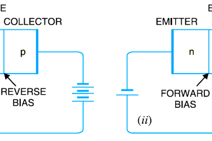
(4) In BJT, the saturation means, base is completely flooded with carriers. Therefore current flows from collector to emitter.
Ohmic region can disappear fast when gate voltage is removed in the MOSFET. But in BJT, the stored charges in base are removed slowly.

Don't Miss Our Updates
Be the first to get exclusive content straight to your email.
We promise not to spam you. You can unsubscribe at any time.
Invalid email address
You've successfully subscribed !

Continue Reading

Transistor Biasing
Dependent Current Source
Basics of Ohm’s Law
Zener Diode Breakdown Characteristics
VI Characteristic of a Diode
Power MOSFET
Share This Article
Facebook Whatsapp Whatsapp LinkedIn Copy Link
Share
Leave a Comment

Leave a Reply Cancel reply

Your email address will not be published. Required fields are marked *

Stay Connected

128.3kFollowersLike
69.1kFollowersFollow
210kSubscribersSubscribe
38kFollowersFollow

Categories

Explore More

Methods of Transistor Biasing
Diodes Voltage Tripler
PIN Diode Working Principle
Bipolar Junction Transistor Construction
How to Test a Diode using Multimeter
Full Wave Voltage Doubler using Diodes
Transistor as an Amplifier in Common Emitter
Why Silicon is preferred over Germanium ?

Keep Learning

full-wave-bridge-rectifier-with-voltage-regulator

Basics of Voltage Regulators

phototransistor symbols

Phototransistor Working Principle

Cathode Ray Tube Deflection System

Cathode Ray Tube Deflection System

Basics of Amplifiers Interview Questions

Amplifiers Questions & Answers

Diode Rectifier

Bridge Rectifier Working Animation

Comparison of Half wave Rectifiers and Full wave Rectifiers

Comparison of Half wave Rectifiers and Full wave Rectifiers

transistor-terminals

Basics of Transistors

Combining Independent Current Sources in Parallel

Combining Independent Current Sources in Parallel

Learn More

What is Profibus

What is Profibus? – A Comprehensive Guide for Beginners

Pressure Gauges with Zero Adjustment

Pressure Gauges Zero Adjustment

Power Electronics Objective Questions

Power Electronics Applications Objective Questions

Thermocouple Temperature Ranges

Thermocouple Temperature Range Questions and Answers

Temperature Control System Example

Chemical Reactor Temperature Control System

MicroElectronics and Integrated Circuits Objective Questions and Answers

MicroElectronics and Integrated Circuits Objective Questions and Answers

Digital Electronics Multiple Choice Questions

Memory Devices Objective Questions – Part 5

Technical Specification for Uninterrupted Power Supply (UPS) System

Technical Specification for Uninterrupted Power Supply (UPS) System

Menu

  • About
  • Privacy Policy
  • Copyright

Quick Links

  • Learn PLC
  • Helping Hand
  • Part Time Job

YouTube Subscribe

Follow US
All rights reserved. Reproduction in whole or in part without written permission is prohibited.
Welcome Back!

Sign in to your account

Username or Email Address
Password

Lost your password?