Inst ToolsInst ToolsInst Tools
  • Courses
  • Automation
    • PLC
    • Control System
    • Safety System
    • Communication
    • Fire & Gas System
  • Instrumentation
    • Design
    • Pressure
    • Temperature
    • Flow
    • Level
    • Vibration
    • Analyzer
    • Control Valve
    • Switch
    • Calibration
    • Erection & Commissioning
  • Interview
    • Instrumentation
    • Electrical
    • Electronics
    • Practical
  • Q&A
    • Instrumentation
    • Control System
    • Electrical
    • Electronics
    • Analog Electronics
    • Digital Electronics
    • Power Electronics
    • Microprocessor
  • Request
Search
  • Books
  • Software
  • Projects
  • Process
  • Tools
  • Basics
  • Formula
  • Power Plant
  • Root Cause Analysis
  • Electrical Basics
  • Animation
  • Standards
  • 4-20 mA Course
  • Siemens PLC Course
Reading: Level Measurement with Dry leg and Installed Below Tapping Point
Share
Notification Show More
Font ResizerAa
Inst ToolsInst Tools
Font ResizerAa
  • Courses
  • Design
  • PLC
  • Interview
  • Control System
Search
  • Courses
  • Automation
    • PLC
    • Control System
    • Safety System
    • Communication
    • Fire & Gas System
  • Instrumentation
    • Design
    • Pressure
    • Temperature
    • Flow
    • Level
    • Vibration
    • Analyzer
    • Control Valve
    • Switch
    • Calibration
    • Erection & Commissioning
  • Interview
    • Instrumentation
    • Electrical
    • Electronics
    • Practical
  • Q&A
    • Instrumentation
    • Control System
    • Electrical
    • Electronics
    • Analog Electronics
    • Digital Electronics
    • Power Electronics
    • Microprocessor
  • Request
Follow US
All rights reserved. Reproduction in whole or in part without written permission is prohibited.
Inst Tools > Blog > Instrumentation Tools > Level Measurement with Dry leg and Installed Below Tapping Point

Level Measurement with Dry leg and Installed Below Tapping Point

Last updated: November 12, 2019 3:18 pm
Editorial Staff
Instrumentation Tools Level Measurement
2 Comments
Share
1 Min Read
SHARE
Closed Tank Level Measurement with Dry leg and Transmitter installed below Tapping Point
Level Measurement with Dry leg and Installed Below Tapping Point
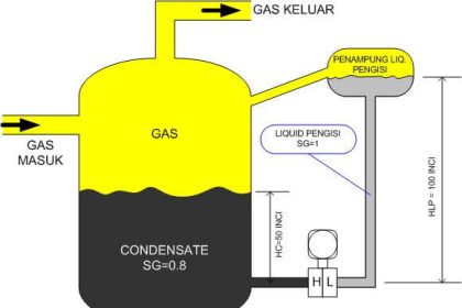
This calculation used for closed tank level measurement with Dry leg type calibration

The formulas for calculating transmitter URV and LRV are as follows:

 HP Side or LRV or Transmitter 0%    =  X.S
 LP Side or URV or Transmitter 100% =  S(X+H)

Where
S    =  Specific gravity of tank liquid or process liquid.
H   =  Tank Height
X   =   Distance between transmitter and HP tapping point.

NOTE:
1. The Parameters H,X can be entered in any units like mmh20, inh20 but must be same

Don't Miss Our Updates
Be the first to get exclusive content straight to your email.
We promise not to spam you. You can unsubscribe at any time.
Invalid email address
You've successfully subscribed !

Continue Reading

Float Type Level Indicator Principle
Siemens Pressure Transmitter with Remote Seals Calculations
Level Measurement with Wet leg and Installed Below Tapping Point
Open Tank DP Level Transmitter Calculations
RTD Calculator : Calculate Temperature from Resistance
Level Transmitter Animation
Share This Article
Facebook Whatsapp Whatsapp LinkedIn Copy Link
Share
2 Comments
  • Anonymous says:
    April 15, 2015 at 6:41 am

    Hmm…Its a good tool for having a tool to calculate instrument range for DP Level Transmitter wet leg type. Good One.

    Reply
  • Bidhan Das says:
    December 16, 2016 at 5:58 am

    I have done accordingly but LT is going into analog saturation

    Reply

Leave a Reply Cancel reply

Your email address will not be published. Required fields are marked *

Stay Connected

128.3kFollowersLike
69.1kFollowersFollow
210kSubscribersSubscribe
38kFollowersFollow

Categories

Explore More

Magnetostrictive Level Measurement
Types of Industrial Level Sensors
Magnetic Level Gauge Float Design
Servo Tank Gauges Working Principle
Level Gauge Design
Effect of Temperature & Pressure on Level Measurement
What is Reflex Level Gauge?
Level Measurement Terminology

Keep Learning

Magnetic Level Indicator

Magnetic Level Indicator Principle, Limitations, Installation and Calibration

Transparent Level Gauge

Level Indicators Working Principle

Micro-impulse Level Transmitter Principle

Micro-impulse Level Transmitter Principle

Radar Level Transmitter in Briddle level Measurement

Radar Level Transmitter in Briddle level Measurement

Tilt Level Switch Theory

Tilt Level Switch Working Principle

Surface Detector Level Measurement System

Surface Detector Level Gauges (Plumb-bob)

Displacer Level Transmitter weight calibration

Displacer Level Transmitter Dry Calibration with Weights

DP-Level-Transmitter-Open-tank-calibration

Open Tank DP Level Transmitter Calibration

Learn More

Top 100 Electrical Machines Projects for Electrical Engineers

Top 100 Electrical Machines Projects for Electrical Engineers

Compare Serial and Parallel Communication

Difference Between Serial and Parallel Communication

Production Planning Software

Production Planning with Technology – Software, Advantages

Instrumentation Lab Viva Questions

Instrumentation Lab Viva Questions

Digital Control Systems

The inverse z-transform & Response of Linear Discrete Systems

How to Design a Motor Faceplate in Graphics - SCADA Tutorials

How to Design a Motor Faceplate in Graphics? – SCADA Tutorials

Delete Siemens CPU Memory

How to Delete the Siemens CPU Memory?

surface-mounted water pump

Surface-mounted Water Pump

Menu

  • About
  • Privacy Policy
  • Copyright

Quick Links

  • Learn PLC
  • Helping Hand
  • Part Time Job

YouTube Subscribe

Follow US
All rights reserved. Reproduction in whole or in part without written permission is prohibited.
Welcome Back!

Sign in to your account

Username or Email Address
Password

Lost your password?