Design a PLC Ladder Logic for Chemical Mixing Process. We have RSLogix 500 PLC Programming software to create PLC logic and its simulation.
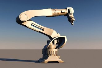
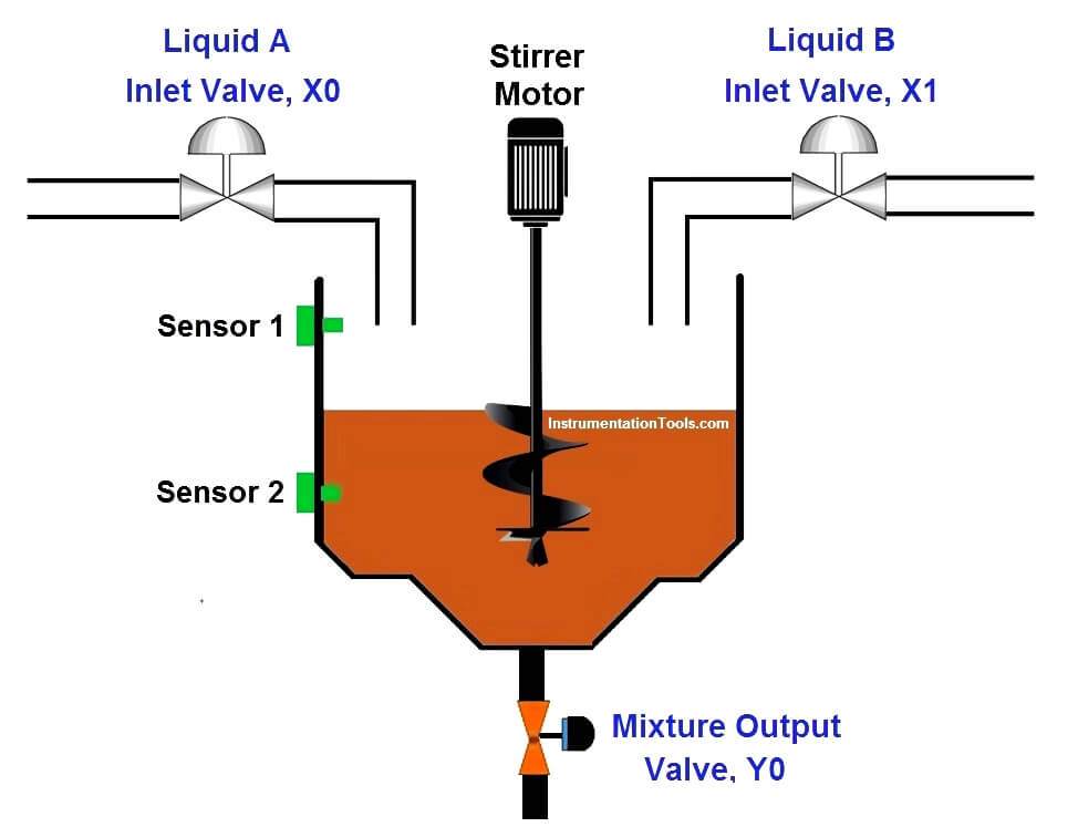
PLC Chemical Mixing Process
Problem Logic
Step Conditions:
- Liquid A valve should ON till Sensor 2 activates
- Liquid B valve should ON between Sensor 1 and sensor 2 activation.
- After Sensor 2 activation, Stirrer motor should be ON for 10sec for stirring process.
- After stirring, Mixture output valve should open for 10sec.
- Process should continue still stop push button pressed.
List of Inputs and Outputs
| S.no | Address | Name | Input/output |
| 1 | I:0/0 | Start | Input |
| 2 | I:0/1 | Stop | Input |
| 3 | I:0/2 | Sensor 2 | Input |
| 4 | I:0/3 | Sensor 1 | Input |
| 5 | O:0/1 | Liquid A inlet Valve 1 | Output |
| 6 | O:0/1 | Liquid B inlet Valve 1 | Output |
| 7 | O:0/2 | Stirrer Motor | Output |
| 8 | O:0/3 | Outlet Valve | Output |
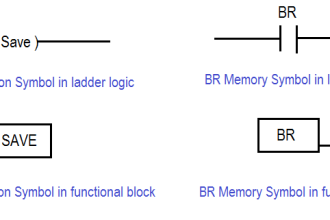
| 9 | B3:0 | Memory bits | Memory |
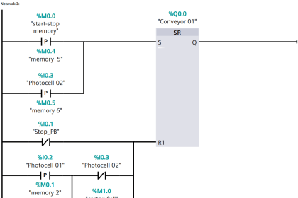
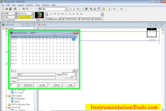
PLC Program :


Ladder Logic Description
RUNG000
Latching rung to operate the system through Master Start and Stop PB.
RUNG001 and RUNG0002
To turn on liquid A input valve using memory bit of start latching PB, it will automatically turn off once Sensor 2 activates
RUNG 0003 and RUNG 0004
To turn on liquid B input valve using Sensor 2 activation, it will automatically turn off once Sensor 1 activates
Rung 0005
To store the status of Sensor 1, memory bit is used.
Rung 0006
On delay timer is used to run the stirrer motor for 10 sec .
RUNG 0007
On delay timer is used to Outlet valve for 10 sec .
Program runs continuously until STOP PB is pressed.
Note:
- Memory bits are used to store the sensor output, since it is the simulation, sensor cannot turn off automatically.
- Memory bits are used to get the sequence of operation.
Conclusion:
The above explained Chemical Mixing process is for example only. It may vary from real time. We can use this example program to understand the working of timers, memory bit and interlocking concept function in AB PLC.
If you liked this article, then please subscribe to our YouTube Channel for PLC and SCADA video tutorials.
You can also follow us on Facebook and Twitter to receive daily updates.
Read Next: