Inst ToolsInst ToolsInst Tools
  • Courses
  • Automation
    • PLC
    • Control System
    • Safety System
    • Communication
    • Fire & Gas System
  • Instrumentation
    • Design
    • Pressure
    • Temperature
    • Flow
    • Level
    • Vibration
    • Analyzer
    • Control Valve
    • Switch
    • Calibration
    • Erection & Commissioning
  • Interview
    • Instrumentation
    • Electrical
    • Electronics
    • Practical
  • Q&A
    • Instrumentation
    • Control System
    • Electrical
    • Electronics
    • Analog Electronics
    • Digital Electronics
    • Power Electronics
    • Microprocessor
  • Request
Search
  • Books
  • Software
  • Projects
  • Process
  • Tools
  • Basics
  • Formula
  • Power Plant
  • Root Cause Analysis
  • Electrical Basics
  • Animation
  • Standards
  • 4-20 mA Course
  • Siemens PLC Course
Reading: Cathode Ray Tube (CRT)
Share
Font ResizerAa
Inst ToolsInst Tools
Font ResizerAa
  • Courses
  • Design
  • PLC
  • Interview
  • Control System
Search
  • Courses
  • Automation
    • PLC
    • Control System
    • Safety System
    • Communication
    • Fire & Gas System
  • Instrumentation
    • Design
    • Pressure
    • Temperature
    • Flow
    • Level
    • Vibration
    • Analyzer
    • Control Valve
    • Switch
    • Calibration
    • Erection & Commissioning
  • Interview
    • Instrumentation
    • Electrical
    • Electronics
    • Practical
  • Q&A
    • Instrumentation
    • Control System
    • Electrical
    • Electronics
    • Analog Electronics
    • Digital Electronics
    • Power Electronics
    • Microprocessor
  • Request
Follow US
All rights reserved. Reproduction in whole or in part without written permission is prohibited.
Inst Tools > Blog > Electronic Devices & Circuits > Cathode Ray Tube (CRT)

Cathode Ray Tube (CRT)

Last updated: April 1, 2018 8:33 am
Editorial Staff
Electronic Devices & Circuits
No Comments
Share
1 Min Read
SHARE

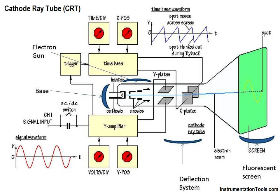
The cathode ray Tube (CRT) is the heart of the C.R.O. the CRT generates the electron beam, accelerates the beam, deflects the beam and also has a screen where beam becomes visible as a spot.

The main parts of the CRT are:

  1. Electron Gun
  2. Deflection system
  3. Fluorescent screen
  4. Glass tube or envelope
  5. Base

A schematic diagram of CRT, showing its structure and main components is shown in the figure below.

Cathode Ray Tube (CRT)

Since I want to explain each and every parts of the CRT in detail, I will split this topic into 3 parts.

Electron Gun of Cathode Ray Tube
Cathode Ray Tube Deflection System
CRT Fluorescent Screen
Don't Miss Our Updates
Be the first to get exclusive content straight to your email.
We promise not to spam you. You can unsubscribe at any time.
Invalid email address
You've successfully subscribed !

Continue Reading

Transistor as a Switch Working Principle
Phototransistor Circuit Example
JFET Working Animation
Capacitor Filter Operation
Why Silicon is preferred over Germanium ?
Laser Diode Working Principle
Share This Article
Facebook Whatsapp Whatsapp LinkedIn Copy Link
Share
Leave a Comment

Leave a Reply Cancel reply

Your email address will not be published. Required fields are marked *

Stay Connected

128.3kFollowersLike
69.1kFollowersFollow
210kSubscribersSubscribe
38kFollowersFollow

Categories

Explore More

Ideal Diode Characteristics
Capacitively Coupled Multistage Transistor Amplifier
Semiconductors Diodes Questions & Answers
Summary Of Transistor Bias Circuits
Combining Independent Voltage Sources in Series
Diode Limiters/Clippers Operation
Forward Bias & Reverse Bias Diode Working Animation
Comparison of Transistor Configurations

Keep Learning

Types-of-diodes

Different Types of Diodes

energy-diagrams-for-insulator-semiconductor-and-conductor

Band Gap for Semiconductor Materials

Open Circuit without Freewheeling diode

Freewheeling Diode Working Principle

Tunnel Diode

Tunnel Diode Working Principle

phototransistor symbols

Phototransistor Working Principle

Optocoupler Principle

Optocouplers Working Principle

Transistor Load Line Analysis

Transistor Load Line Analysis

diode-clamper-circuit

Diode Clampers Principle

Learn More

Difference Between Metering CT and Protection CT

Difference Between Metering CT and Protection CT

Process Control Automation PLC Quiz

Process Control Automation PLC Quiz

AC Generator Operation

Losses in AC Generator

HMI screen for operator

Auto Tiffin Box Filling Station

Group of Induction Motors

How to Operate a Group of Induction Motors using PLC Logic?

Digital Electronics Objective Questions

Digital Electronics Objective Questions – Set 7

fundamentals of an AC motor

How does an Electric Motor Operate? – AC Motor Fundamentals

level of liquid inside a vessel

Concept of Redundancy in Control Systems

Menu

  • About
  • Privacy Policy
  • Copyright

Quick Links

  • Learn PLC
  • Helping Hand
  • Part Time Job

YouTube Subscribe

Follow US
All rights reserved. Reproduction in whole or in part without written permission is prohibited.
Welcome Back!

Sign in to your account

Username or Email Address
Password

Lost your password?