Inst ToolsInst ToolsInst Tools
  • Courses
  • Automation
    • PLC
    • Control System
    • Safety System
    • Communication
    • Fire & Gas System
  • Instrumentation
    • Design
    • Pressure
    • Temperature
    • Flow
    • Level
    • Vibration
    • Analyzer
    • Control Valve
    • Switch
    • Calibration
    • Erection & Commissioning
  • Interview
    • Instrumentation
    • Electrical
    • Electronics
    • Practical
  • Q&A
    • Instrumentation
    • Control System
    • Electrical
    • Electronics
    • Analog Electronics
    • Digital Electronics
    • Power Electronics
    • Microprocessor
  • Request
Search
  • Books
  • Software
  • Projects
  • Process
  • Tools
  • Basics
  • Formula
  • Power Plant
  • Root Cause Analysis
  • Electrical Basics
  • Animation
  • Standards
  • 4-20 mA Course
  • Siemens PLC Course
Reading: Car Wash Program using Functional Block Diagram (PLC)
Share
Notification Show More
Font ResizerAa
Inst ToolsInst Tools
Font ResizerAa
  • Courses
  • Design
  • PLC
  • Interview
  • Control System
Search
  • Courses
  • Automation
    • PLC
    • Control System
    • Safety System
    • Communication
    • Fire & Gas System
  • Instrumentation
    • Design
    • Pressure
    • Temperature
    • Flow
    • Level
    • Vibration
    • Analyzer
    • Control Valve
    • Switch
    • Calibration
    • Erection & Commissioning
  • Interview
    • Instrumentation
    • Electrical
    • Electronics
    • Practical
  • Q&A
    • Instrumentation
    • Control System
    • Electrical
    • Electronics
    • Analog Electronics
    • Digital Electronics
    • Power Electronics
    • Microprocessor
  • Request
Follow US
All rights reserved. Reproduction in whole or in part without written permission is prohibited.
Inst Tools > Blog > PLC Tutorials > Car Wash Program using Functional Block Diagram (PLC)

Car Wash Program using Functional Block Diagram (PLC)

Learn how to program an automatic car wash system using functional block diagrams. A beginner-friendly guide for PLC programmers.

Last updated: September 17, 2024 11:44 am
Viral Nagda
PLC Tutorials
No Comments
Share
5 Min Read
SHARE

The functional block diagram is a language in PLC programming which is very easy to use and best for troubleshooting, due to its wide graphical representation scope. Even a new programmer will find it easy to understand.

Contents
Car Wash ProgramFunctional Block Diagram (PLC)

We will learn one sample program in this language in this post. The system we will use for reference is an automatic car wash function. For this system, we will write the logic in a functional block diagram, so that the programmers find it easy to understand and interpret.

Car Wash Program

First, let us understand the case scenario. There are three PLC digital inputs – the start push button, the stop push button, and the car sensor. There are two PLC digital outputs – sprinkler and soap bubbler.

The system has four sequences – first, it will wash, then it will soap, then it will rinse and at last, it will soak. After soaking, the system will stop automatically and wait for a new car.

The sequence starts by pressing the start button and only when a car is sensed. In between the sequence, if the stop button is pressed or if the car is not sensed, then the whole cycle will reset and wait for a new start once again.

Functional Block Diagram (PLC)

Now that we are clear with the scenario of the program required, let us write the logic in a functional block diagram. Refer to the below image. We will see the whole sequence step by step now.

Car Wash Program using Functional Block Diagram (PLC)

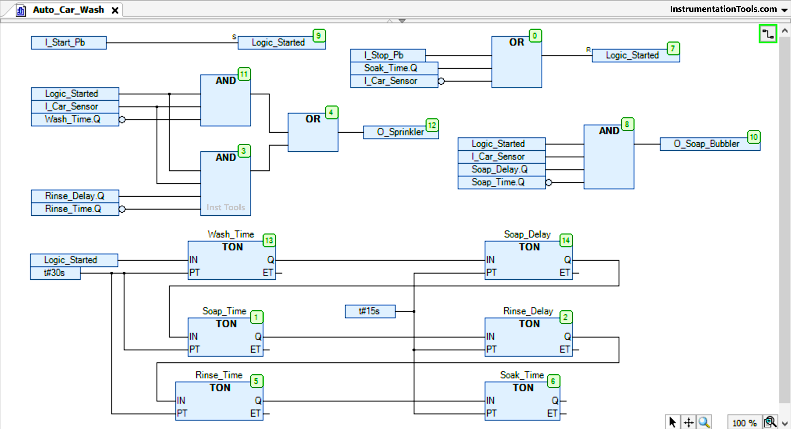
We set a bit named – logic started on pressing the start button. The same bit is reset on three conditions – when the stop button is pressed, or when the car is not sensed, or when soaking time is over. Refer to the first top two parts in the image.

The first output of the sprinkler will turn on only during wash time and rinse time. So, for the sprinkler, we have used two AND blocks and one common OR block. Both the AND blocks will have two common interlocks – logic running and car sensor.

In the first AND block, we used the wash timer done bit as negate. It means it will run only till the wash timer is running and stop once the timer is done.

In the second AND block, we used the rinse delay timer done bit and rinse timer done bit as negate. It means it will run only when the rinse delay timer is complete and till the rinse timer is running. Once the rinse timer is done, it will stop.

The second output of the soap bubbler will turn on only when the soap delay timer is complete and till the soap timer is running. Once the soap timer is done, it will stop. For this, we used the soap delay timer done bit and soap timer done bit as negate. It will also have both the common interlocks- logic running and car sensor.

Now, let us see the timer logic. As we see, when the logic is started, the wash time starts for 30 seconds. After it is over, it starts the soap delay timer for 15 seconds. After it is over, it starts the soap timer for 30 seconds.

After it is over, it starts the rinse delay timer for 15 seconds. After it is over, it starts the rinse timer for 30 seconds. After it is over, it starts the soak timer for 15 seconds.

After this timer, the logic is reset as seen in the first condition written. We just linked the timer done of a preceding one to the input of the next one.

In this way, we saw how to write an automatic car washer system using a functional block diagram.

Read Next:

  • Structured Text PLC Logic for Motor Interlock
  • How Modbus is used in Industrial Networks?
  • Conveyor Speed Logic using Structured Text
  • Burglar Alarm Security System PLC FBD Logic
  • PLC Structured Text Program for Outputs
Don't Miss Our Updates
Be the first to get exclusive content straight to your email.
We promise not to spam you. You can unsubscribe at any time.
Invalid email address
You've successfully subscribed !

Continue Reading

PLC based Drink Dispenser System
PLC Example to Control LEDs Via Switches
How-to do Security of SCADA Systems?
How Engineers Effectively do Problem-solve and Troubleshoot?
Control Algorithms in PLC Programming
Down Counter PLC Program
Share This Article
Facebook Whatsapp Whatsapp LinkedIn Copy Link
Share
Leave a Comment

Leave a Reply Cancel reply

Your email address will not be published. Required fields are marked *

Stay Connected

128.3kFollowersLike
69.1kFollowersFollow
210kSubscribersSubscribe
38kFollowersFollow

Categories

Explore More

Hardwired I/O and Serial I/O – Differences Explained
Use of Isolators and Barriers in Electrical Panel
Augmented Reality and Virtual Reality in Industrial Automation
Why is 24 Volts Commonly used in PLC Systems?
PLC Analog Signals Wiring Techniques
Toggle Switch & Sensor: Conveyor and Puncher PLC Program
Safety Door Interlock PLC Program
How to Work with Allen Bradley RsLogix Emulator?

Keep Learning

PLC Program using Counters

PLC Counters Program

Sample Schematic Template for Systems Architecture Diagram

Design Document for Project Systems Architecture

Online and Diagnostics of Siemens PLC

How to Use Diagnostic Buffer for SIEMENS PLC?

PLC Cabinet

PLC Programming Videos

Distributed Control System Interview Questions

How Could FB and FC Make Me Professional PLC Programmer

How Could FB and FC Make Me Professional PLC Programmer?

Web SCADA HMI

Web-based SCADA HMI Software

Wood Sawing and Blower System PLC Control Design

Wood Sawing and Blower System: PLC Control Design

Learn More

Top 100 Power Systems Projects

Top 100 Power Systems Projects – Electrical Engineering

Absorption Chiller Principle - HVAC System

HVAC Double Effect Absorption Chiller

bimetallic thermometer working principle

Different Types of Thermometers

PLC Program three-phase electric motor

Identify the Problem in the PLC Program

Main Functions of a Multimeter

Interesting Multimeter Functions (And What They Really Do)

Bubble Tube Level measurement

Bubble Tube Level Measurement Principle

In this article, we will learn the difference between Machine Expert Basic and Machine Expert software in Schneider PLC.

Difference between Machine Expert Basic and Machine Expert – Schneider PLC

Measure AC Voltage using Multimeter

How to Measure AC Voltage using Multimeter

Menu

  • About
  • Privacy Policy
  • Copyright

Quick Links

  • Learn PLC
  • Helping Hand
  • Part Time Job

YouTube Subscribe

Follow US
All rights reserved. Reproduction in whole or in part without written permission is prohibited.
Welcome Back!

Sign in to your account

Username or Email Address
Password

Lost your password?