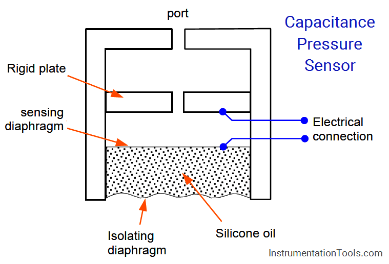
The Capacitive pressure sensor operates on the principle that, if the sensing diaphragm between two capacitor plates is deformed by a differential pressure, an imbalance of capacitance will occur between itself and the two plates.
This imbalance is detected in a capacitance bridge circuit and converted to a D.C. output current of 4 to 20 mA.
This is shown in Figure, where the movement of a flexible diaphragm relative to a fixed plate is sensed by the capacitance change. A secondary isolating diaphragm is used to protect the sensing diaphragm.
Capacitive Pressure Sensor
Another type of capacitor uses concentric hollow metal cylinders. The capacitance of this type just like the flat-plate type is proportional to the area.
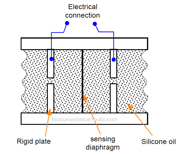
This principle can be applied to differential pressure measurement, as shown in Figure. The pressure acting on the isolating diaphragms set up similar pressures in the silicone oil filling the space between them.
A net force proportional to the difference between the two pressures acts upon the metal sensing diaphragm and deflects it to one side or the other, depending on which input pressure is the greater.
Each plate forms a capacitor with the sensing diaphragm, which is connected electrically to the metallic body transducer.
The sensing diaphragm and capacitor thus form a differential variable separation capacitor. When the two input pressure are equal, the diaphragm is positioned centrally and the capacitances are equal.
A difference in the two input pressures causes displacement of the sensing diaphragm and is sensed as a difference between the two capacitances.
This change in capacitance is measured using a bridge circuit to measure the equivalent pressure signal.
Articles You May Like :
Fieldbus Transmitter Calibration
