Inst ToolsInst ToolsInst Tools
  • Courses
  • Automation
    • PLC
    • Control System
    • Safety System
    • Communication
    • Fire & Gas System
  • Instrumentation
    • Design
    • Pressure
    • Temperature
    • Flow
    • Level
    • Vibration
    • Analyzer
    • Control Valve
    • Switch
    • Calibration
    • Erection & Commissioning
  • Interview
    • Instrumentation
    • Electrical
    • Electronics
    • Practical
  • Q&A
    • Instrumentation
    • Control System
    • Electrical
    • Electronics
    • Analog Electronics
    • Digital Electronics
    • Power Electronics
    • Microprocessor
  • Request
Search
  • Books
  • Software
  • Projects
  • Process
  • Tools
  • Basics
  • Formula
  • Power Plant
  • Root Cause Analysis
  • Electrical Basics
  • Animation
  • Standards
  • 4-20 mA Course
  • Siemens PLC Course
Reading: Calculate Differential Pressure Sensed by Level Transmitter
Share
Font ResizerAa
Inst ToolsInst Tools
Font ResizerAa
  • Courses
  • Design
  • PLC
  • Interview
  • Control System
Search
  • Courses
  • Automation
    • PLC
    • Control System
    • Safety System
    • Communication
    • Fire & Gas System
  • Instrumentation
    • Design
    • Pressure
    • Temperature
    • Flow
    • Level
    • Vibration
    • Analyzer
    • Control Valve
    • Switch
    • Calibration
    • Erection & Commissioning
  • Interview
    • Instrumentation
    • Electrical
    • Electronics
    • Practical
  • Q&A
    • Instrumentation
    • Control System
    • Electrical
    • Electronics
    • Analog Electronics
    • Digital Electronics
    • Power Electronics
    • Microprocessor
  • Request
Follow US
All rights reserved. Reproduction in whole or in part without written permission is prohibited.
Inst Tools > Blog > Practical Questions > Calculate Differential Pressure Sensed by Level Transmitter

Calculate Differential Pressure Sensed by Level Transmitter

Last updated: April 5, 2019 12:25 pm
Editorial Staff
Practical Questions
1 Comment
Share
2 Min Read
SHARE

Calculate Differential Pressure Sensed by Level Transmitter

Question :

Calculate the differential pressure sensed by the level transmitter at three different water levels in this boiler steam-drum level measurement system: The measurable points are 0%, 50%, and 100% of transmitter range.

Drum Level differential pressure transmitter

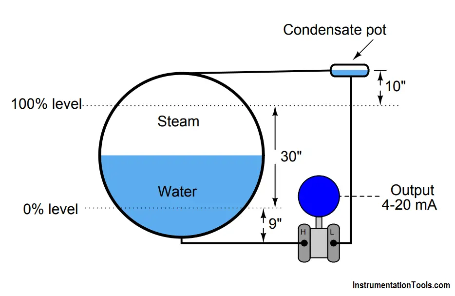
Assume a density for (hot) boiler drum water of 36 lb/ft3 , a density for steam in the drum of 7 lb/ft3 , and a density for (warm) water in the “wet leg” of 61.8 lb/ft3 . If the pressure at the “low” (L) side of the transmitter is greater than the pressure at the “high” (H) side, be sure to express the differential pressure quantity as a negative number.

Credit will be given for correctly calculating each of the differential pressures:

  • (6 points) Transmitter ∆P at 0% water level     = _______”W.C.
  • (6 points) Transmitter ∆P at 50% water level   = _______”W.C.
  • (6 points) Transmitter ∆P at 100% water level = _______”W.C.

Answer :

  1. (6 points) Transmitter ∆P at 0% water level = -38.832 ”W.C.
  2. (6 points) Transmitter ∆P at 50% water level = -31.864 ”W.C.
  3. (6 points) Transmitter ∆P at 100% water level = -24.896 ”W.C.

Also Read : Boiler Drum Level Measurement Principle

Don't Miss Our Updates
Be the first to get exclusive content straight to your email.
We promise not to spam you. You can unsubscribe at any time.
Invalid email address
You've successfully subscribed !

Continue Reading

Pneumatic Force Balance Instrument
What is the Purpose of Chemical Seals Pressure Transmitter?
Simple High Level Indicator Circuit
DP Transmitter Problem
Analytical Process Control Question
Calculate the appropriate millivoltage values of a Thermocouple
Share This Article
Facebook Whatsapp Whatsapp LinkedIn Copy Link
Share
1 Comment
  • quangdinh says:
    June 15, 2022 at 11:15 pm

    Instrument Range:
    LV =[ [( 9″ x 36 + 40″ x 7) – 49″ x 61.8] x 0.0005787037] / 0.036127292000084 lbs/in3
    = – 38.83 ” WC at standard condition
    or LV = – 1.40289 psi
    UV = [ [( 39″ x 36 + 10″ x 7) – 49″ x 61.8] x 0.0005787037] / 0.036127292000084 lbs/in3
    =-24.896″ WC at standard condition
    or UV = -0.89942129054 psi
    Density water at 0.036127292000084 lbs/in3 standard conditions
    Controller Range: -15″ to 15″ WC

    Reply

Leave a Reply Cancel reply

Your email address will not be published. Required fields are marked *

Stay Connected

128.3kFollowersLike
69.1kFollowersFollow
210kSubscribersSubscribe
38kFollowersFollow

Categories

Explore More

Level Measuring Instruments Velocities of Propagation
A Series of False Pressure Alarms
Float-type Level Switch to Control a pump
Calculate 0%, 50%, and 100% Calibration Points for ΔP transmitter
Calculate the Thermocouple’s Measurement Junction Temperature
Fisher model 546 I/P transducer
Process Control Loop Testing
Current-to-Pressure Transducer Calibration Table

Keep Learning

Steam flow to the heat exchanger

Analytical Control System of Heat Exchanger Questions

10 Questions on Reforming Furnace Control System

10 Questions on Reforming Furnace Control System

Pressure Transmitter Re-Range Questions

Pressure Transmitter Re-Range Questions

Questions on Level Switches

Questions on Level Switches

Overhead Product Pressure Control Loop

Overhead Product Pressure Control Loop

calibrating low-pressure instrument

Simulate Different Values for Pressure Instrument Under Test

Radar LT Loop Diagram

Questions on Radar LT Loop Diagram

Calculate LRV and URV for 4-20 mA Loop-powered DP Transmitter

Calculate LRV and URV for 4-20 mA Loop-powered DP Transmitter

Learn More

Power Electronics Objective Questions

Choppers Quiz

Intrinsic semiconductors

Introduction to Semiconductor Electronics – Types, Materials

Process Dynamics and PID Controller Tuning

Process Dynamics and PID Controller Tuning

Calibration Procedure of displacer type Level transmitter

Calibration of Displacer Level Transmitter

Field Transmitter Installation

Cables and Cable Glands Questions and Answers

NACE Standards - MR0103 Vs MR0175

NACE Standards – MR0103 Vs MR0175

WirelessHART field instruments

WirelessHART device Configuration

Valve Non-rising Stems

Valve Functions and Basic Parts of Valve

Menu

  • About
  • Privacy Policy
  • Copyright

Quick Links

  • Learn PLC
  • Helping Hand
  • Part Time Job

YouTube Subscribe

Follow US
All rights reserved. Reproduction in whole or in part without written permission is prohibited.
Welcome Back!

Sign in to your account

Username or Email Address
Password

Lost your password?