Inst ToolsInst ToolsInst Tools
  • Courses
  • Automation
    • PLC
    • Control System
    • Safety System
    • Communication
    • Fire & Gas System
  • Instrumentation
    • Design
    • Pressure
    • Temperature
    • Flow
    • Level
    • Vibration
    • Analyzer
    • Control Valve
    • Switch
    • Calibration
    • Erection & Commissioning
  • Interview
    • Instrumentation
    • Electrical
    • Electronics
    • Practical
  • Q&A
    • Instrumentation
    • Control System
    • Electrical
    • Electronics
    • Analog Electronics
    • Digital Electronics
    • Power Electronics
    • Microprocessor
  • Request
Search
  • Books
  • Software
  • Projects
  • Process
  • Tools
  • Basics
  • Formula
  • Power Plant
  • Root Cause Analysis
  • Electrical Basics
  • Animation
  • Standards
  • 4-20 mA Course
  • Siemens PLC Course
Reading: Calculate 0%, 50%, and 100% Calibration Points for ΔP transmitter
Share
Notification Show More
Font ResizerAa
Inst ToolsInst Tools
Font ResizerAa
  • Courses
  • Design
  • PLC
  • Interview
  • Control System
Search
  • Courses
  • Automation
    • PLC
    • Control System
    • Safety System
    • Communication
    • Fire & Gas System
  • Instrumentation
    • Design
    • Pressure
    • Temperature
    • Flow
    • Level
    • Vibration
    • Analyzer
    • Control Valve
    • Switch
    • Calibration
    • Erection & Commissioning
  • Interview
    • Instrumentation
    • Electrical
    • Electronics
    • Practical
  • Q&A
    • Instrumentation
    • Control System
    • Electrical
    • Electronics
    • Analog Electronics
    • Digital Electronics
    • Power Electronics
    • Microprocessor
  • Request
Follow US
All rights reserved. Reproduction in whole or in part without written permission is prohibited.
Inst Tools > Blog > Practical Questions > Calculate 0%, 50%, and 100% Calibration Points for ΔP transmitter

Calculate 0%, 50%, and 100% Calibration Points for ΔP transmitter

Calculate 0%, 50%, and 100% calibration points for the ΔP transmitter to measure liquid level in the vessel for wet leg and dry leg.

Last updated: November 14, 2020 11:02 am
Editorial Staff
Practical Questions
3 Comments
Share
2 Min Read
SHARE

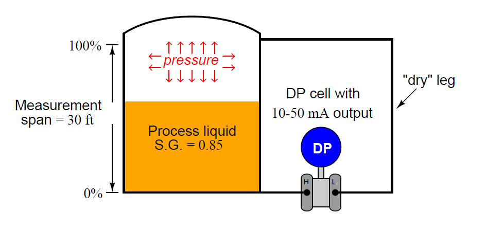
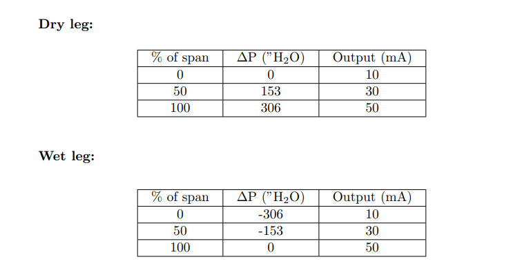
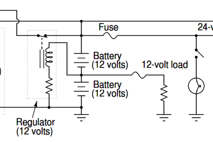
Calculate the 0%, 50%, and 100% calibration points for the ΔP transmitter to measure liquid level in this vessel, given a range of 0 to 30 feet and a specific gravity of 0.85.

Contents
Dry LegWet Leg

Note that the “low” side of the transmitter connects to the top of the vessel to compensate for vapor pressure inside the vessel. This tube (or leg) is called a “dry leg” because there is no liquid inside of it:

Dry Leg

Dry Leg

Now suppose the vessel is heated, and the liquid inside the vessel emits condensible vapors. These vapors will condense inside low-side tube leading to the ΔP transmitter which is cooler than the storage vessel, resulting in a “wet leg” instead of a “dry leg.”

In other words, the transmitter will now “see” a constant column of liquid (SG = 0.85) 30 feet high connected to its “low” process port:

Wet Leg

Wet Leg

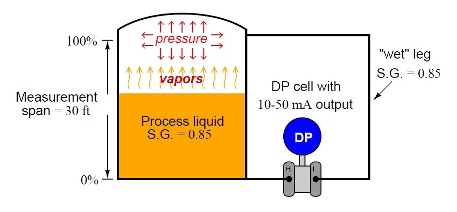
Re-calculate the 0%, 50%, and 100% calibration points for the ΔP transmitter to measure liquid level in this vessel with a wet reference leg instead of a dry reference leg.

Answers:

Calculate 0%, 50%, and 100% Calibration Points for ΔP transmitter

Share your answers with us through below comments section.

Read Next:

  • DP Transmitter with 5 Way Manifold
  • Question on Analytical Controller
  • Loop Powered Pressure Transmitter
  • PLC Practice Questions
  • Questions on Chemical Reactor P & ID

Credits: Tony R. Kuphaldt

Don't Miss Our Updates
Be the first to get exclusive content straight to your email.
We promise not to spam you. You can unsubscribe at any time.
Invalid email address
You've successfully subscribed !

Continue Reading

Calculate the Thermocouple’s Measurement Junction Temperature
Compressor Emergency Shutdown Root Cause Analysis
PLC Practice Questions
Pneumatic Level Transmitter Value Struck?
Determine the Temperature of 3 Wire RTD
How Overload Heaters used to Automatically Shut the Motor OFF ?
Share This Article
Facebook Whatsapp Whatsapp LinkedIn Copy Link
Share
3 Comments
  • mubin says:
    November 16, 2020 at 6:18 am

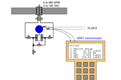
    why u put the answer use 50mA?

    Reply
    • shah says:
      November 16, 2020 at 9:44 am

      As per the image, I think it is assumed 10 to 50 mA as output current range of DP transmitter.

      Reply
  • chin weng fong says:
    November 22, 2020 at 5:59 pm

    how to install calibration range and full range and check distance

    Reply

Leave a Reply Cancel reply

Your email address will not be published. Required fields are marked *

Stay Connected

128.3kFollowersLike
69.1kFollowersFollow
210kSubscribersSubscribe
38kFollowersFollow

Categories

Explore More

Guided-wave Radar Asset Management Parameters
Thermocouple Measurement and Reference Junction Temperatures
Practical Process Control System Questions & Answers – 6
Determine the Problems with Level Transmitter and Gauge
Transmitter Calibration Range of a Vessel Level
How Nuclear Radiation is used to Measure Coke Dust Level?
Questions on Pneumatic Transmitter and Repeater
10 Questions on Reforming Furnace Control System

Keep Learning

Remote Seal Pressure Transmitter Temperature

Importance of Temperature in Remote Seal Pressure Transmitter

Stilling well in liquid level measurement

Stilling Well in Interface Level Measurement System

Guided wave radar Measurement Principle

Instrument Salesperson Question

Allen-Bradley MicroLogix controller

Programmable Logic Controller (PLC) Questions and Answers – 16

Determine the statuses of all lamps and relay coils in the circuit

Determine the Status of Lamps and Relays in the Circuit ?

LRV and URV of PT for Extreme Limits of Empty and Full

LRV and URV of PT for Extreme Limits of Empty and Full

Heat Exchanger Differential Pressure Transmitter

Heat Exchanger Differential Pressure Transmitter

Double Block and Bleed Valves Opening or Closing Sequence

Double Block and Bleed Valves Opening or Closing Sequence

Learn More

HVAC Refrigeration Cycle

HVAC Refrigeration Cycle

Orifice Plate Sizing

Orifice Sizing Guidelines and Thumb Rules with Flowchart

Difference between LVDT and RVDT

Difference between LVDT and RVDT?

Conductivity measurement

Conductivity Measurement

PLC Programming Example on Multi-Motor Control for Beginners

PLC Programming Example on Multi-Motor Control for Beginners

Functional Safety Exam Questions & Answers

Functional Safety Questions & Answers

Deluge Valve Operation using Solenoid Valve Animation

Deluge Valve Operation

Pressure gauges with capsule elements

Pressure Gauges with Capsule Sensor Principle

Menu

  • About
  • Privacy Policy
  • Copyright

Quick Links

  • Learn PLC
  • Helping Hand
  • Part Time Job

YouTube Subscribe

Follow US
All rights reserved. Reproduction in whole or in part without written permission is prohibited.
Welcome Back!

Sign in to your account

Username or Email Address
Password

Lost your password?