With the time demand of increasing the efficiency of production facilities to achieve Target, it is required to made the engineering system robust and fool proof .The below described is used for various systems and subsystems in the industries and are backed up with practical success .The modification is very helpful in achieving the high end target, increased production capacities ,reduction in human effort and make a WIN WIN situation for the both employees and employers.
Description of system
The blast furnace operations normally using bell operations for charging & employ the services of pneumatic cylinders for operation. These cylinders are operated by pneumatic solenoid valves which are switched on and off by PLC control system. For continuous operations of the furnace, the complete system needs to be healthy.
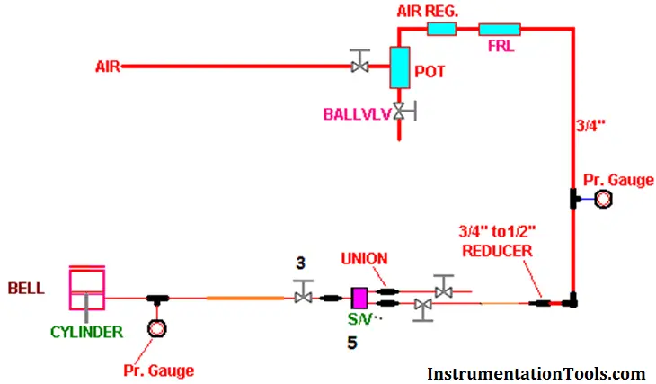
Standalone System panel (Existing System)
The available solenoid valve system are generally are of standalone type system where any malfunction/breakdown of solenoid valve will take a long time of say around 30-40 minutes to remove the valve and place a new valve in line. Thus for a huge system like blast furnace the 40 minutes breakdown cost are very high.
The schematic diagram of the standalone system (Fig 1) is indicated below; in this the solenoid valve S/V 5 is operated as per requirement of furnace. The manual valve 3 is put in open condition. The charging frequency depends on the charging mode of the furnace.
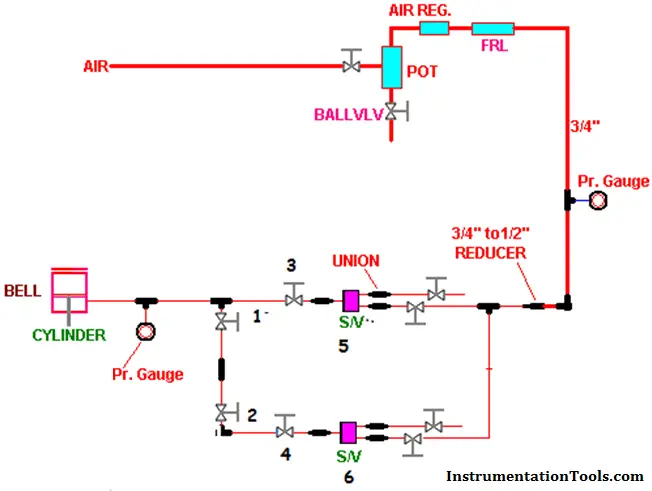
Modified panel: (Modified System)
The pneumatic system is little bit modified (Shown below Fig 2) with the putting up of a branch line and the spare solenoid valve as shown in below picture. Here one additional solenoid valve indicated by S/V 6 is placed in system .along with this we have placed simple manual on/off valves indicated by NO 1, 2 and 4.
In normal operation the solenoid S/V 5 remains in working and manual valve 1 is placed in open condition. The manual valves 1, 2 and 4 are in closed position.
Once the things are done ,the breakdown if occurs in the solenoid valve ,the manual valves 3 is closed .after this manual valves 1,2,& 4 are opened .This facilitates for taking S/V 6 in to system ,simultaneously the coil from the existing solenoid valve S/V 5 is to be placed on the spares solenoid valve ,thus the system is healthy for charging the furnace.
The system can be put back in operation within a span of 10-15 minutes at the most against the normally 30-40 minutes required with a standalone system
Another advantage is that the work is done by only 1 technician in shifts,
Thus the system can help to minimize the downtime of system on account of solenoid valve failure.
Article Written by:
Sh. Pravin V. Maheshkar
Management & technical consultant/trainer Freelance
Previously Manager –Inst & Business excellence
(Hindustan zinc ltd ,Echjay steels ltd,total:23 yrs)





I am Regular Reader of this website. Good Article. Thank you Pravin V Maheshkar sir.
thanks and my pleasure.If you need any professional help ,I am available on pravinmaheshkar1969@gmail.com