Inst ToolsInst ToolsInst Tools
  • Ask
  • Courses
  • Videos
  • Q & A
    • Interview
      • Instrumentation
      • Electronics
      • Electrical
      • Practical Questions
    • MCQ
      • Instrumentation MCQ
      • Electrical MCQ
      • Electronics MCQ
      • Control Systems MCQ
      • Analog Electronics MCQ
      • Digital Electronics MCQ
      • Power Electronics MCQ
      • Microprocessor MCQ
      • Multiple Choice Questions
  • EE
    • Electronics
      • Electronics Q & A
      • Electronic Basics
      • Electronic Devices & Circuits
      • Electronics Animation
      • Digital Electronics
    • Electrical
      • Electrical Basics
      • Electrical Q & A
      • Power Electronics
      • Electrical Machines
      • Electrical Animation
      • Power Systems
      • Switchgear & Protection
      • Transmission & Distribution
  • Measure
    • Control Valves
    • Calibration
    • Temperature
    • Pressure
    • Flow
    • Level
    • Analyzers
    • Switches
    • Vibration
    • Solenoid Valve
  • Control
    • PLC Tutorials
    • Control Systems
    • Safety Instrumented System (SIS)
    • Communication
    • Fire & Gas System
  • More
    • Design
    • Tools
    • Animation
    • Basics
    • Formulas
    • Standards
    • TextBooks
    • Common
    • Software
    • Excel Tools
    • Erection & Commissioning
    • Process Fundamentals
    • Videos
    • Books
Search
All rights reserved. Reproduction in whole or in part without written permission is prohibited.
Reading: Basics of Ohm’s Law
Share
Notification Show More
Font ResizerAa
Inst ToolsInst Tools
Font ResizerAa
  • Courses
  • PLC Tutorials
  • Control Systems
Search
  • Ask
  • Courses
  • Videos
  • Q & A
    • Interview
    • MCQ
  • EE
    • Electronics
    • Electrical
  • Measure
    • Control Valves
    • Calibration
    • Temperature
    • Pressure
    • Flow
    • Level
    • Analyzers
    • Switches
    • Vibration
    • Solenoid Valve
  • Control
    • PLC Tutorials
    • Control Systems
    • Safety Instrumented System (SIS)
    • Communication
    • Fire & Gas System
  • More
    • Design
    • Tools
    • Animation
    • Basics
    • Formulas
    • Standards
    • TextBooks
    • Common
    • Software
    • Excel Tools
    • Erection & Commissioning
    • Process Fundamentals
    • Videos
    • Books
Follow US
All rights reserved. Reproduction in whole or in part without written permission is prohibited.
Inst Tools > Blog > Electronic Devices & Circuits > Basics of Ohm’s Law

Basics of Ohm’s Law

Last updated: December 31, 2017 5:34 am
Editorial Staff
Electronic Devices & Circuits
1 Comment
Share
2 Min Read
SHARE

In 1827 the German physicist George Ohm published a pamphlet entitled “The Galvanic Circuit Investigated Mathematically”. It contained one of the first efforts to measure currents and voltages and to describe and relate them mathematically. One result was a statement of the fundamental relationship we now call Ohm’s Law.

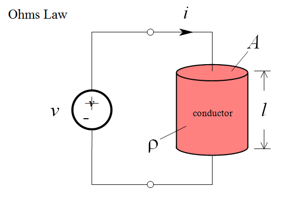
Consider a uniform cylinder of conducting material, to which a voltage has been connected. The voltage will cause charge to flow, i.e. a current:

Derivation-of-Ohms-Law

Ohm found that in many conducting materials, such as metal, the current is always proportional to the voltage. Since voltage and current are directly proportional, there exists a proportionality constant R, called resistance, such that:

Ohms-Law

This is Ohm’s Law. The unit of resistance (volts per ampere) is referred to as the ohm, and is denoted by the capital Greek letter omega, Ω.

We refer to a construction in which Ohm’s Law is obeyed as a resistor.

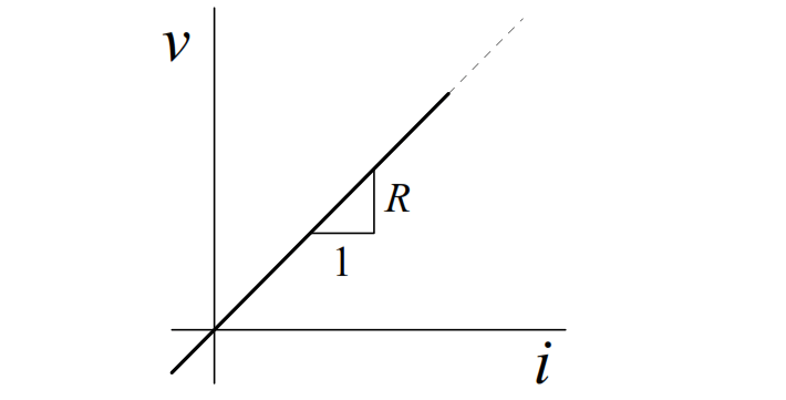
The ideal resistor relationship is a straight line through the origin:

Ohms-Law-Resistor-Linearity

Even though resistance is defined as R = v/i , it should be noted that R is a purely geometric property, and depends only on the conductor shape and the material used in the construction. For example, it can be shown for a uniform resistor that the resistance is given by:

Resistance-Equation

where l is the length of the resistor, and A is the cross-sectional area. The resistivity,  r ,  is  a  constant  of  the conducting  material  used  to  make  the resistor.

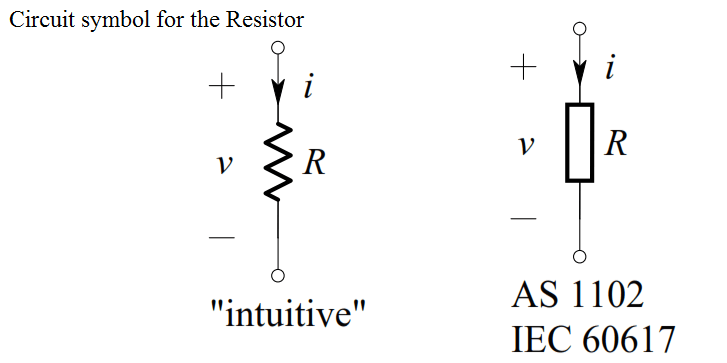
The circuit symbol for the resistor is shown below, together with the direction of current and polarity of voltage that make Ohm’s Law algebraically correct:

circuit-symbol-for-the-resistor

Example

Consider the circuit shown below.

Ohms-Law-Example

The voltage across the 1 kΩ resistor is, by definition of an ideal voltage source,

v(t ) = 10 V . Thus, by Ohm’s Law, we get:

i1  =  v/R = 10/1000 = 0.01 A = 10 mA

i2  =  –v/R = -10/1000 = -0.01 A = -10 mA

Note that i2  = –i1 , as expected
Don't Miss Our Updates
Be the first to get exclusive content straight to your email.
We promise not to spam you. You can unsubscribe at any time.
Invalid email address
You've successfully subscribed !
Transistor Emitter Feedback Bias
Troubleshooting a Biased Transistor
Transistor as an Amplifier in Common Emitter
Choke Input Filter Operation
Transistor as Amplifier
Share This Article
Facebook Whatsapp Whatsapp LinkedIn Copy Link
Share
1 Comment
  • Azum Blaise Gabriel says:
    November 10, 2021 at 5:25 pm

    Very interesting and helpful.
    Young and upcoming engineers should take note

    Reply

Leave a Reply Cancel reply

Your email address will not be published. Required fields are marked *

Stay Connected

128.3kFollowersLike
69.1kFollowersFollow
208kSubscribersSubscribe
38kFollowersFollow

Categories

Recent Comments

  • Kamli on Top Free PLC Software
  • Guifty Shimica on Top Non-PLC Certification Courses for Automation Professionals
  • Guifty Shimica on Top Non-PLC Certification Courses for Automation Professionals
  • MIHARITSOA Aina Sitraka on Top Non-PLC Certification Courses for Automation Professionals

Related Articles

Ideal Diode Characteristics

Ideal Diode Characteristics

Transistors Questions & Answers

Transistors Questions & Answers

Full Wave Rectifier Peak Inverse Voltage

Full Wave Bridge Rectifier Peak Inverse Voltage

Basics of Amplifiers Interview Questions

Amplifiers Questions & Answers

Basic Transistor Amplifier Circuit Principle

Basic Transistor Amplifier Circuit Principle

Zener Diode Limiter Working

Zener Diode Limiter

example-of-KCL

What is Kirchhoff’s Current Law

What is a Filter Circuit

What is a Filter Circuit ?

More Articles

Inductive Time Constant

Inductive Time Constant

PID Controller Functionality

PID Controller Theory

Annubar Flow Meter Principle

Annubar Flow Meter – Principle, Advantages, Disadvantages

Proportional Band example

Why Offset in Proportional Controller ?

GC sample loop

Chromatograph Sample Valves

PLC Based Metro Automation Project

PLC based Metro Automation Project

thermal imaging instrument

Thermal Imaging Temperature Measurement

Internal Parts of Globe Valve

How to Choose a Control Valve?

Follow US
All rights reserved. Reproduction in whole or in part without written permission is prohibited.
Welcome Back!

Sign in to your account

Username or Email Address
Password

Lost your password?