This article will discuss a Sequential Control System that can be operated in either Auto or Manual mode using XGB PLC program. The system will control four Lamps to turn on sequentially in a specific order. All lights will turn on at specific intervals, and the timer’s preset value can be adjusted. When the system is running in Manual mode, each Lamp can only be turned on using a button.
Program Objective
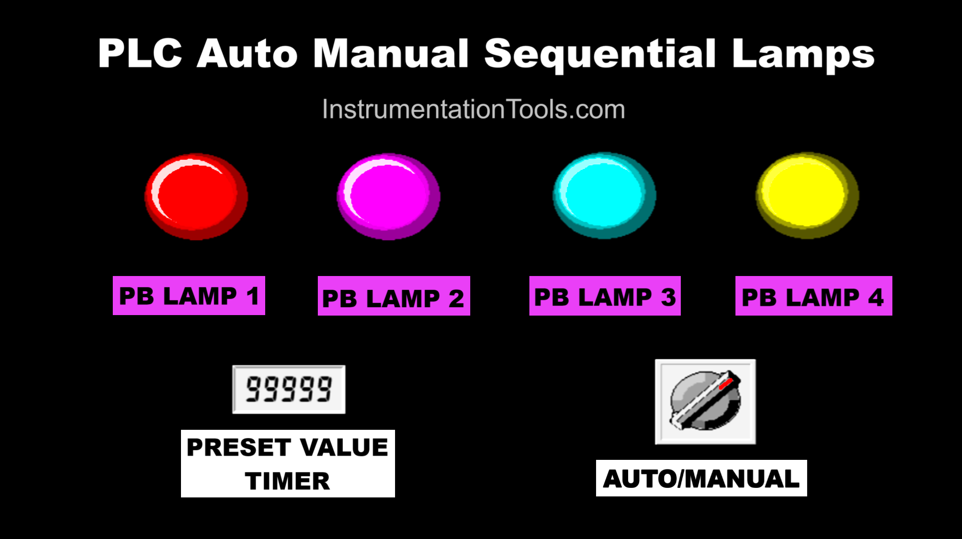
Sequence System:
Auto Mode: The selector switch needs to be changed to the “Auto” position to run the system in Automatic mode. In this mode, the Preset Value Timer parameter needs to be set.
Manual Mode: The selector switch needs to be changed to the “Manual” position. Each lamp can only be turned on by its corresponding button.
When the system has been run in “Auto” mode:
- Lamp-1 turns On.
- Lamp-1 turns Off and Lamp-2 turns On.
- Lamp-2 turns Off and Lamp-3 turns On.
- Lamp-3 turns Off and Lamp-4 turns On.
- All lamps will turn on again in the same sequence with the same time interval.
When the system has been run in “Manual” mode:
- Button-1 turns On Lamp-1.
- Button-2 turns On Lamp-2.
- Button-3 turns On Lamp-3.
- Button-4 turns On Lamp-4.
XGB PLC Program to Control 4 Lamps
Mapping Details
| S.No. | Comment | Input (I) | Output (Q) | Memory Word | Memory Bit | Timer |
|---|---|---|---|---|---|---|
| 1 | START | P0000 | ||||
| 2 | STOP | P0001 | ||||
| 3 | SELECTOR_SWITCH | P0002 | ||||
| 4 | PB_LAMP1 | P0003 | ||||
| 5 | PB_LAMP2 | P0004 | ||||
| 6 | PB_LAMP3 | P0005 | ||||
| 7 | PB_LAMP4 | P0006 | ||||
| 8 | LAMP1 | P0040 | ||||
| 9 | LAMP2 | P0041 | ||||
| 10 | LAMP3 | P0042 | ||||
| 11 | LAMP4 | P0043 | ||||
| 12 | TIMER1 | T000 | ||||
| 13 | TIMER2 | T001 | ||||
| 14 | TIMER3 | T002 | ||||
| 15 | TIMER4 | T003 | ||||
| 16 | SYSTEM_ON | M0000 | ||||
| 17 | IR_LAMP1 | M0001 | ||||
| 18 | IR_LAMP2 | M0002 | ||||
| 19 | IR_LAMP3 | M0003 | ||||
| 20 | IR_LAMP4 | M0004 | ||||
| 21 | SV_TIMER | D0000 |
Auto Manual Sequential Lamps Operation
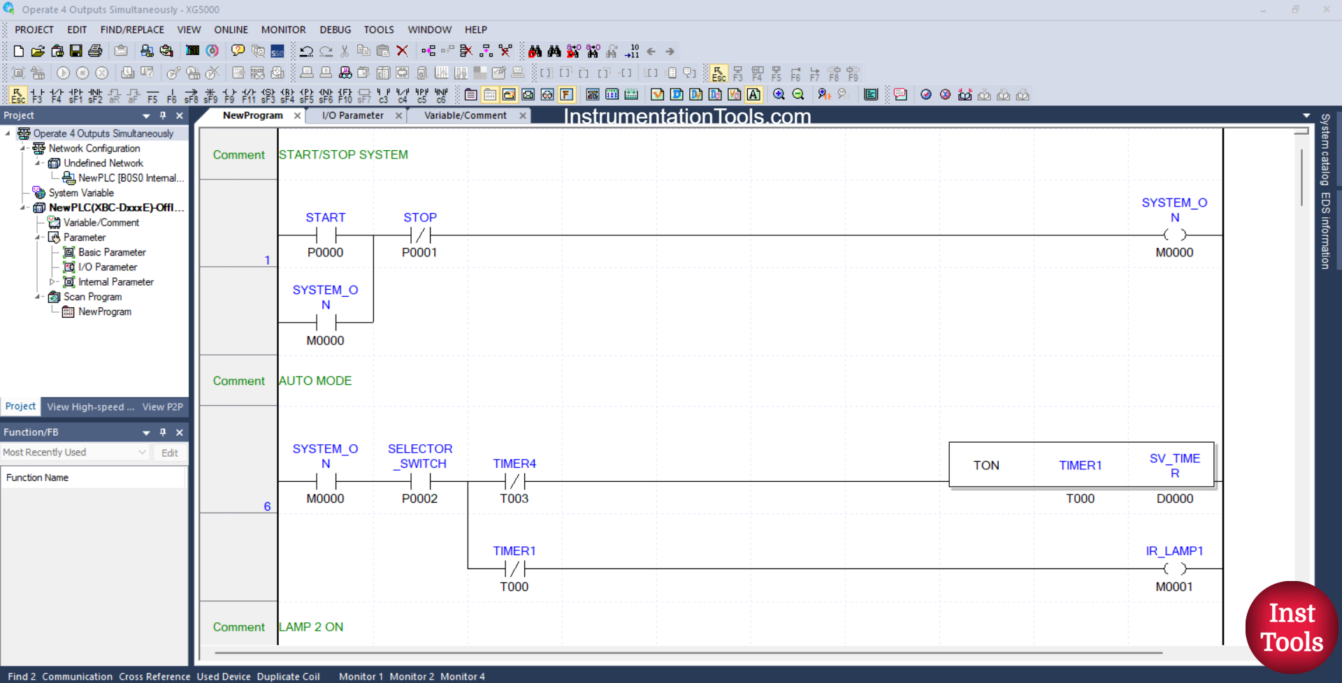
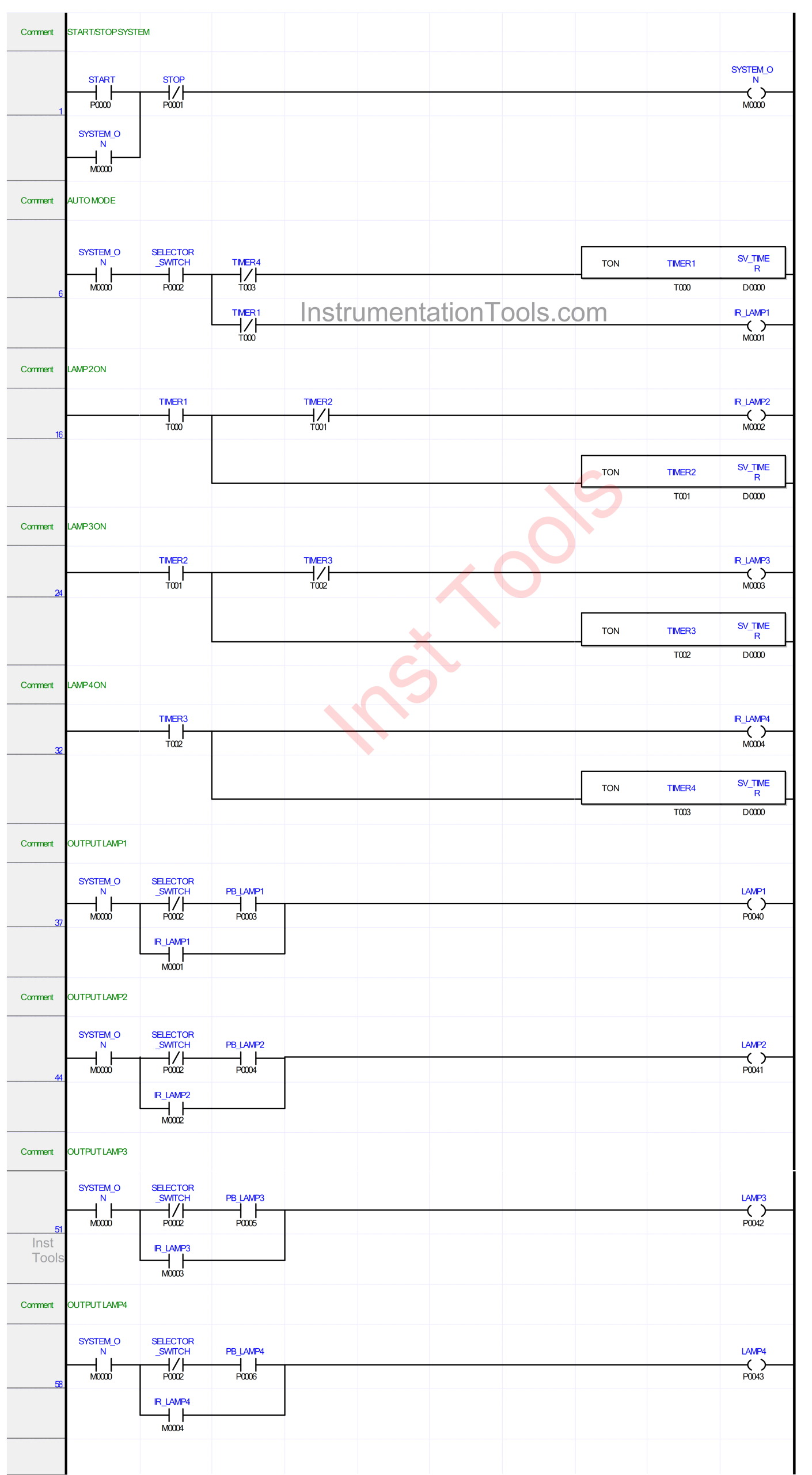
RUNG 1 (START/STOP SYSTEM)
In this Rung, the memory bit SYSTEM_ON (M0000) will be in the HIGH state when the START (P0000) button is pressed. Because it uses Latching, the memory bit SYSTEM_ON (M0000) will remain in the HIGH state even though the START(P0000) button has been released.
The memory bit SYSTEM_ON (M0000) will be in the LOW state if the STOP (P0001) button is pressed.
RUNG 6 (AUTO MODE)
In this Rung, when the NO contact of the memory bit SYSTEM_ON (M0000) and the NO contact of Selector Switch SELECTOR_SWITCH (P0002) are in the HIGH state, then Timer TIMER1 (T000) will start counting and the memory bit IR_LAMP1 (M0001) will be in the HIGH state.
Timer TIMER1 (T000) will count down according to the value that has been set in the memory word SV_TIMER (D0000).
When Timer TIMER1 (T000) has finished counting, the memory bit IR_LAMP1 (M0001) will be in the LOW state.
Timer TIMER1 (T000) will be reset when the NC contact of Timer TIMER4 (T003) is in the HIGH state.
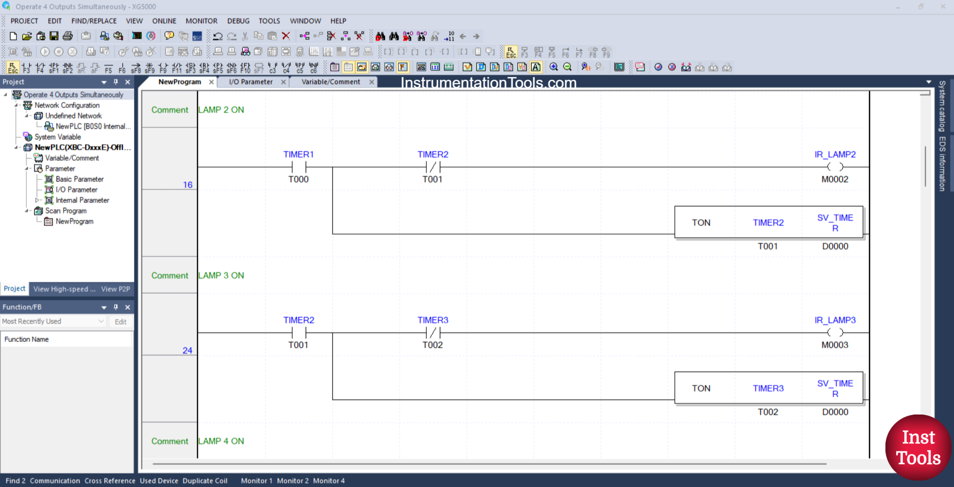
RUNG 16 (LAMP 2 ON)
In this Rung, when the NO contact of Timer TIMER1 (T000) is in the HIGH state, the memory bit IR_LAMP2 (M0002) becomes in the HIGH state, and Timer TIMER2 (T001) will start counting.
Timer TIMER2 (T001) will count down according to the value that has been set in the memory word SV_TIMER (D0000).
RUNG 24 (LAMP 3 ON)
In this Rung, when the NO contact of Timer TIMER2 (T001) is in the HIGH state, the memory bit IR_LAMP3 (M0003) becomes in the HIGH state, and Timer TIMER3 (T002) will start counting.
Timer TIMER3 (T002) will count down according to the value that has been set in the word memory SV_TIMER (D0000).
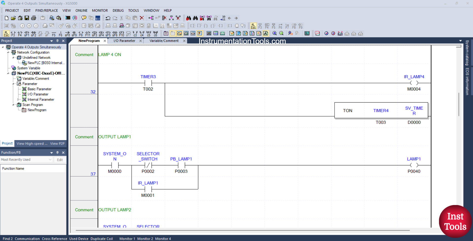
RUNG 32 (LAMP 4 ON)
In this Rung, when the NO contact of Timer TIMER3 (T002) is in the HIGH state, the memory bit IR_LAMP4 (M0004) becomes in the HIGH state, and Timer TIMER4 (T003) will start counting.
Timer TIMER4 (T003) will count down according to the value that has been set in the memory word SV_TIMER (D0000).
RUNG 37 (OUTPUT LAMP1)
In this Rung, when the NO contact of the memory bit SYSTEM_ON (M0000) is in the HIGH state, the NC contact of the Selector Switch SELECTOR_SWITCH (P0002) is in the LOW state, and the PB_LAMP1 (P0003) button has been pressed, then the LAMP_1 (P0040) output will be ON.
Or, if the NO contact of the memory bit IR_LAMP1 (M0001) is in the HIGH state, then the output of LAMP_1 (P0040) will be ON.
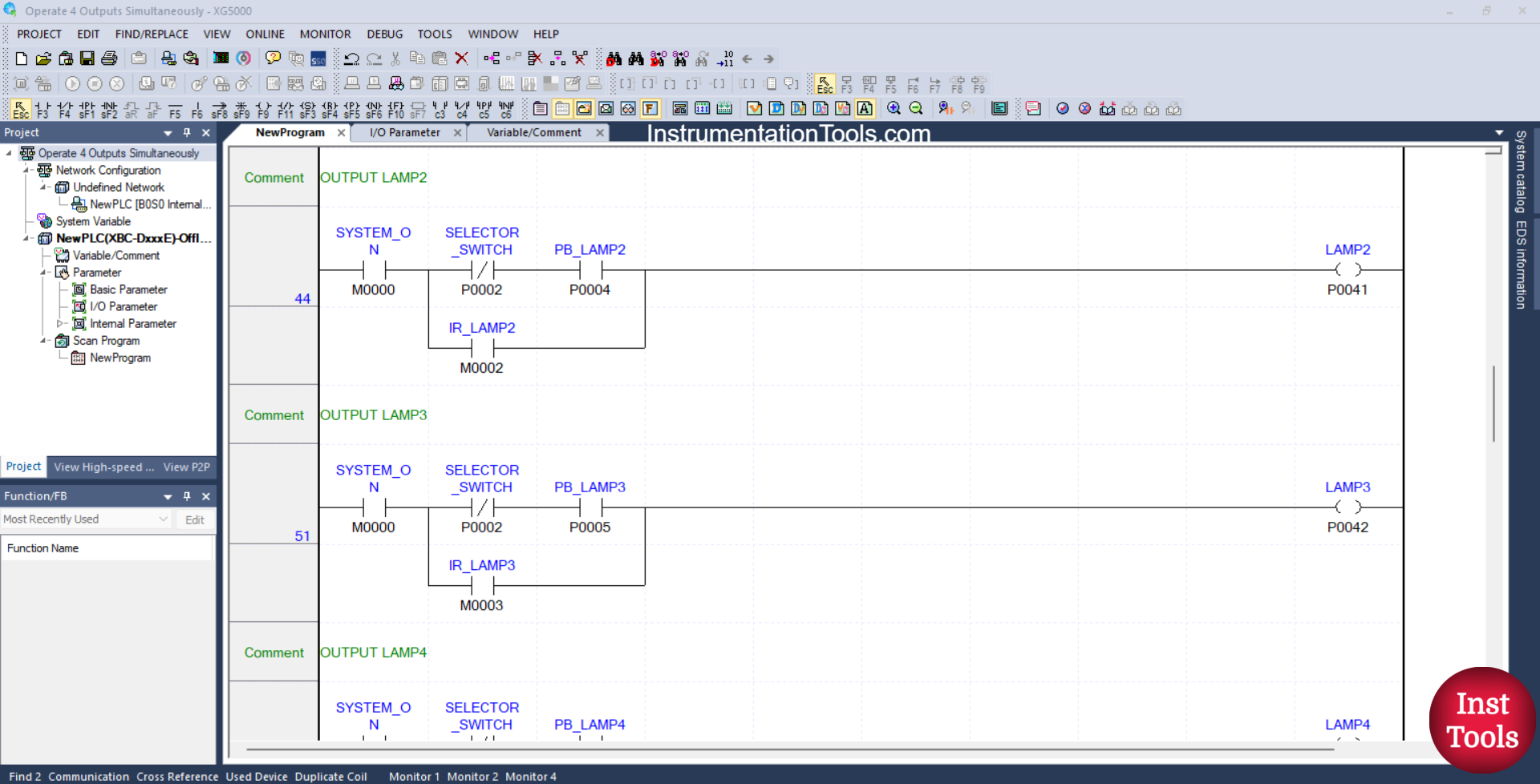
RUNG 44 (OUTPUT LAMP2)
In this Rung, when the NO contact of the memory bit SYSTEM_ON (M0000) is in the HIGH state, the NC contact of the Selector Switch SELECTOR_SWITCH (P0002) is in the LOW state, and the PB_LAMP2 (P0004) button has been pressed, then the LAMP2 (P0041) output will be ON.
Or, if the NO contact of the memory bit IR_LAMP2 (M0002) is in the HIGH state, then the output LAMP2 (P0041) will be ON.
RUNG 51 (LAMP3 OUTPUT)
In this Rung, when the NO contact of the memory bit SYSTEM_ON (M0000) is in the HIGH state, the NC contact of the Selector Switch SELECTOR_SWITCH (P0002) is in the LOW state, and the PB_LAMP3 (P0005) button has been pressed, then the LAMP3 (P0042) output will be ON.
Or, if the NO contact of the memory bit IR_LAMP3 (M0003) is in the HIGH state, then the output LAMP3 (P0042) will be ON.
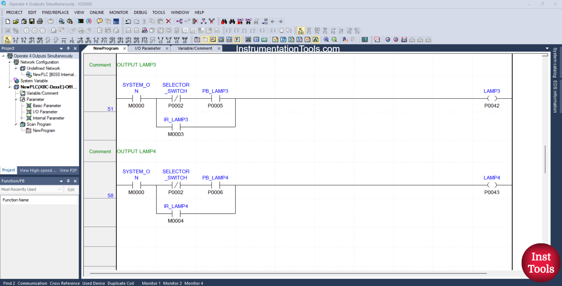
RUNG 58 (LAMP4 OUTPUT)
In this Rung, when the NO contact of the memory bit SYSTEM_ON (M0000) is in the HIGH state, the NC contact of the Selector Switch SELECTOR_SWITCH (P0002) is in the LOW state, and the PB_LAMP4 (P0006) button has been pressed, then the LAMP4 (P0043) output will be ON.
Or, if the NO contact of the memory bit IR_LAMP4 (M0004) is in the HIGH state, then the output LAMP4 (P0043) will be ON.
Read Next:
- Cargo Elevator System Using PLC Programming
- Object Detection Based Door Opening PLC System
- PLC Bottle Quality Inspection Using Vision Sensor
- Upload Option Disabled in Siemens PLC Tutorial
- PID Controller with Practical Example Explained