This article will discuss the aquaculture automation system using SIMATIC PLC programming. The PLC will be programmed to automatically control actuators such as water pumps, aerators, and feed valves. The pH, temperature, and water level sensor data will be connected to the PLC to monitor pool conditions in real-time. Data obtained from the sensors will be processed by the system and compared to predetermined setpoints. The system will activate an alarm if the pH and water temperature values exceed the setpoints.
Program Objective
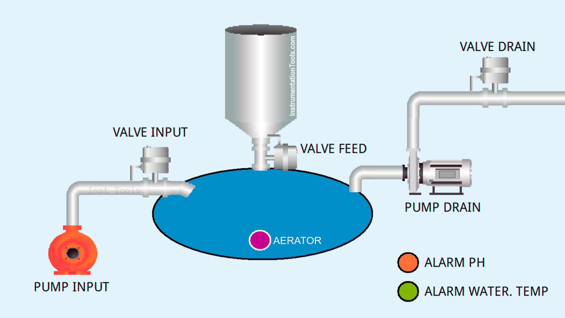
Initialization: When the system is turned on, the Aerator will automatically turn on to start air circulation in the pond.
Feeding Cycle: Every 8 seconds, the valve will open to provide food to the fish.
Water Quality Monitoring:
- The pH sensor will continuously monitor the acidity level of the water. If the pH value is outside the range of 5-7, an alarm will sound.
- The temperature sensor will continuously monitor the water temperature. If the temperature is above 35°C or below 26°C, an alarm will sound.
Water Level Control:
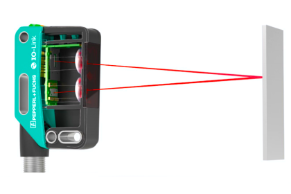
- The level sensor will continuously monitor the water level in the pond.
- If the water level is below the minimum level (low level), the pump will automatically turn on to fill the water.
- If the water level is above the maximum limit (high level), the pump will automatically turn on to remove excess water.
Mapping Details
| S.No. | Comment | Input (I) | Output (Q) | Memory Words | Memory Bits | Timer |
|---|---|---|---|---|---|---|
| 1 | START | I0.0 | ||||
| 2 | STOP | I0.1 | ||||
| 3 | WATER_LEVEL_LOW | I0.2 | ||||
| 4 | WATER_LEVEL_HIGH | I0.3 | ||||
| 5 | AERATOR | Q0.0 | ||||
| 6 | VALVE_FISH_FEED | Q0.1 | ||||
| 7 | ALARM1 | Q0.2 | ||||
| 8 | ALARM2 | Q0.3 | ||||
| 9 | VALVE_INPUT_WATER | Q0.4 | ||||
| 10 | PUMP_INPUT_WATER | Q0.5 | ||||
| 11 | VALVE_DRAIN_WATER | Q0.6 | ||||
| 12 | PUMP_DRAIN_WATER | Q0.7 | ||||
| 13 | PV_WATER_PH | MW0 | ||||
| 14 | WATER_TEMPERATURE | MW2 | ||||
| 15 | TIMER1 | DB1 | ||||
| 16 | TIMER2 | DB2 | ||||
| 17 | TIMER3 | DB3 | ||||
| 18 | TIMER4 | DB4 | ||||
| 19 | SYSTEM_ON | M0.0 | ||||
| 20 | IR_TIMER2 | M0.2 |
PLC Program for Aquaculture System
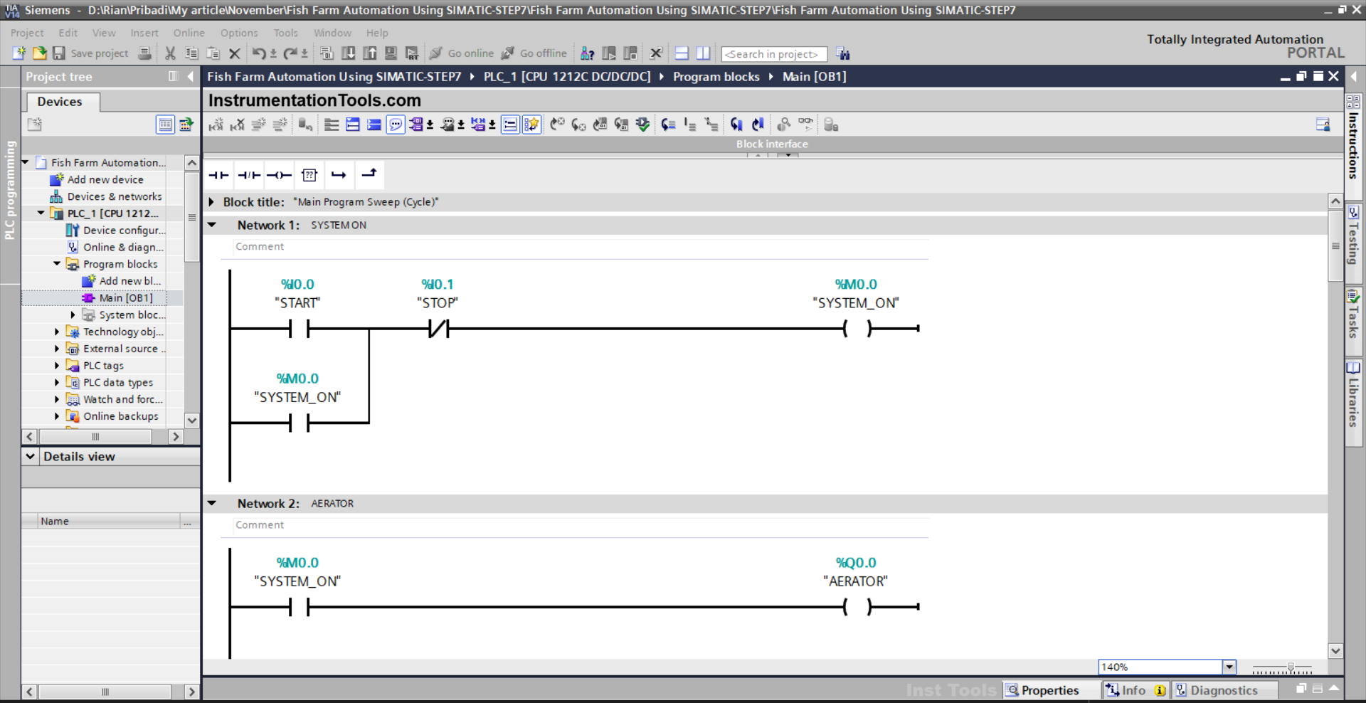
NETWORK 1 (SYSTEM ON)
In this Network, the memory bit SYSTEM_ON (M0.0) will be in a HIGH state when the PB_START (I0.0) button is pressed. Due to latching, the memory bit SYSTEM_ON (M0.0) will remain in a HIGH state even though the PB_START (I0.0) button is released.
When the PB_STOP (I0.1) button is pressed, the memory bit SYSTEM_ON (M0.0) will be in a LOW state.
NETWORK 2 (AERATOR)
In this Network, the output AERATOR (Q0.0) will be ON if the NO contact of the memory bit SYSTEM_ON (M0.0) is in a HIGH state.
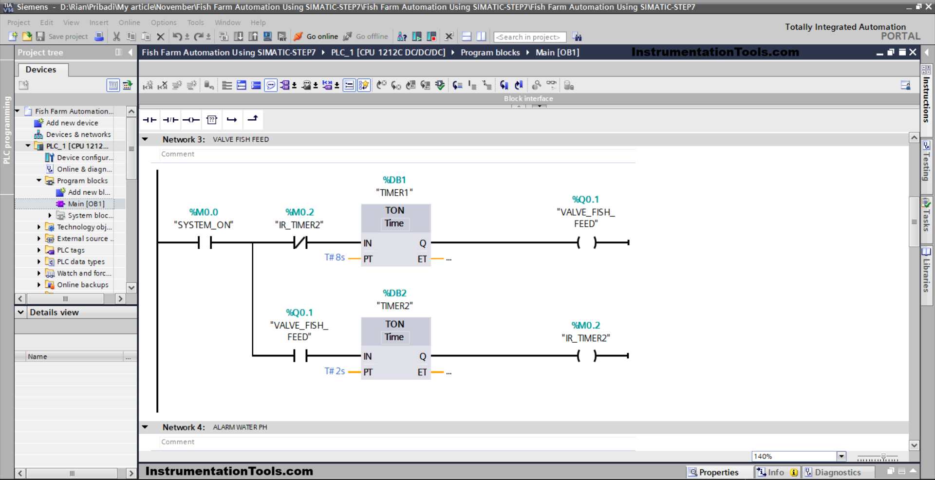
NETWORK 3 (VALVE FISH FEED)
In this Network, Timer TIMER1 (DB1) will start counting up to 8 seconds when the NO contact of the memory bit SYSTEM_ON (M0.0) is in the HIGH state, and when Timer TIMER1 (DB1) has finished counting, the output VALVE_FISH_FEED (Q0.1) will become OPEN.
Next, Timer TIMER2 (DB2) will start counting up to 2 seconds, and after it has finished counting, the memory bit IR_TIMER2 (M0.2) will be in a HIGH state.
Timer TIMER1 (DB1) will be reset, and the output VALVE_FISH_FEED (Q0.1) will return to CLOSED when the NC contact of the memory bit IR_TIMER2 (M0.2) is in a HIGH state.
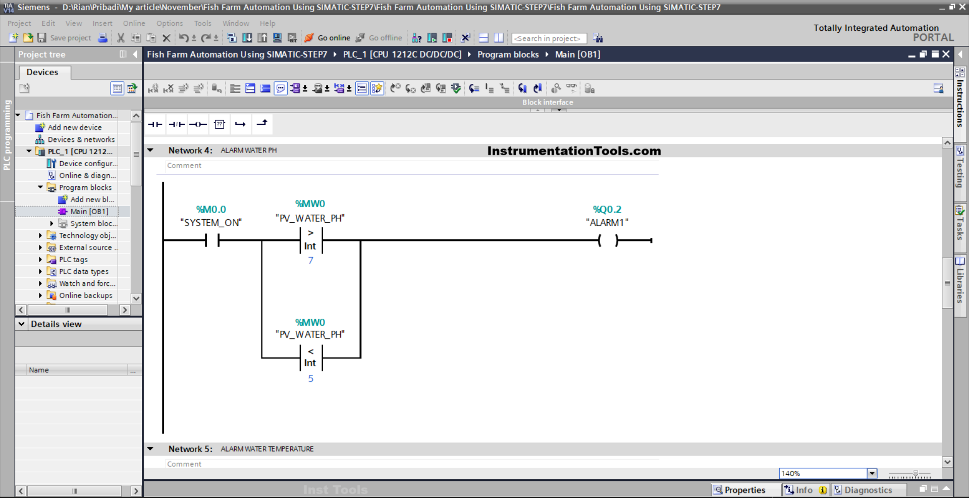
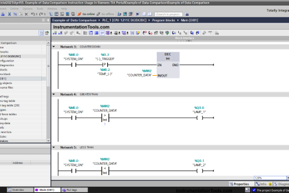
NETWORK 4 (WATER PH ALARM)
In this Network, Output ALARM1 (Q0.2) will be ON when the NO contact of the memory bit SYSTEM_ON (M0.0) in the HIGH state and the value in the memory word PV_WATER_PH (MW0) is Greater Than “7” or Less Than “5 ”.
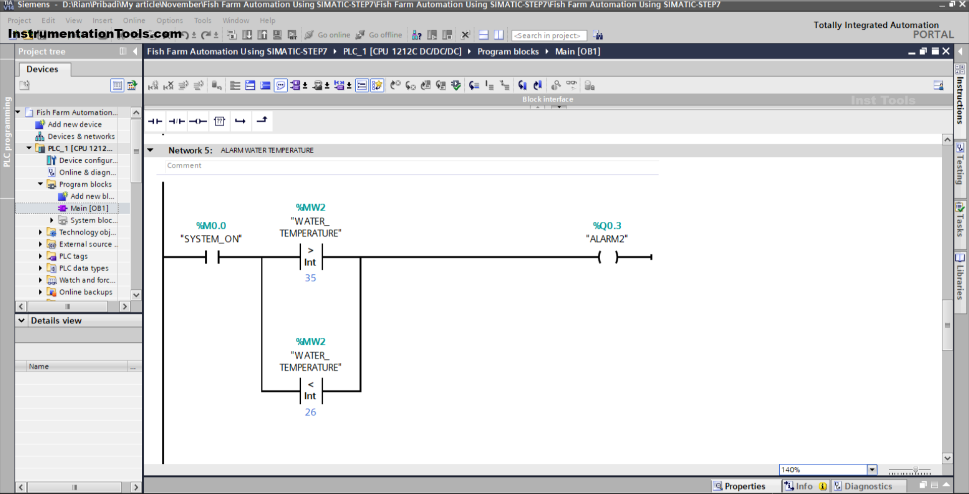
NETWORK 5 (WATER TEMPERATURE ALARM)
In this Network, Output ALARM2 (Q0.3) will be ON when the NO contact of the memory bit SYSTEM_ON (M0.0) in the HIGH state and the value of the memory word WATER_TEMPERATURE (MW2) is Greater Than “35” or Less Than “26 ”.
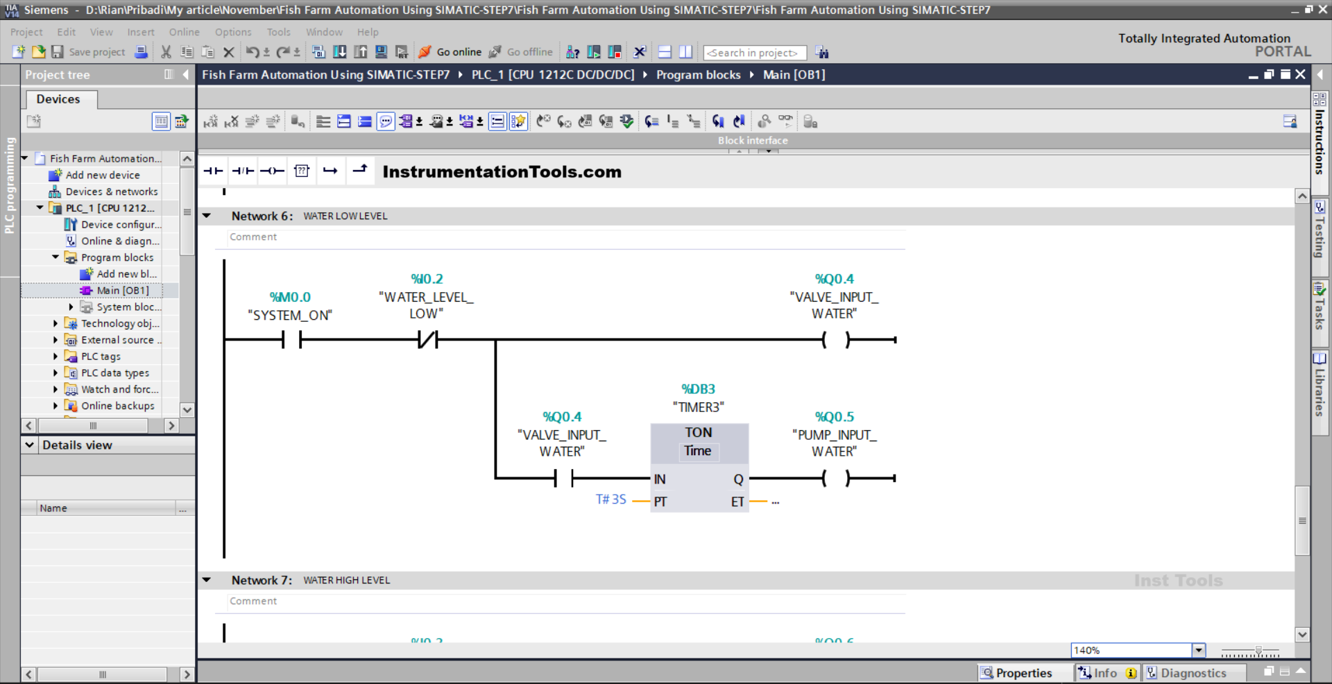
NETWORK 6 (WATER LOW LEVEL)
In this Network, the output VALVE_INPUT_WATER (Q0.4) will be OPEN when the NO contact of the memory bit SYSTEM_ON (M0.0) is in the HIGH state.
The timer TIMER3 (DB3) will start counting up to 3 seconds when the NO contact of the output VALVE_INPUT_WATER (Q0.4) is in the HIGH state.
When Timer TIMER3 (DB3) has finished counting, the output PUMP_INPUT_WATER (Q0.5) will become ON.
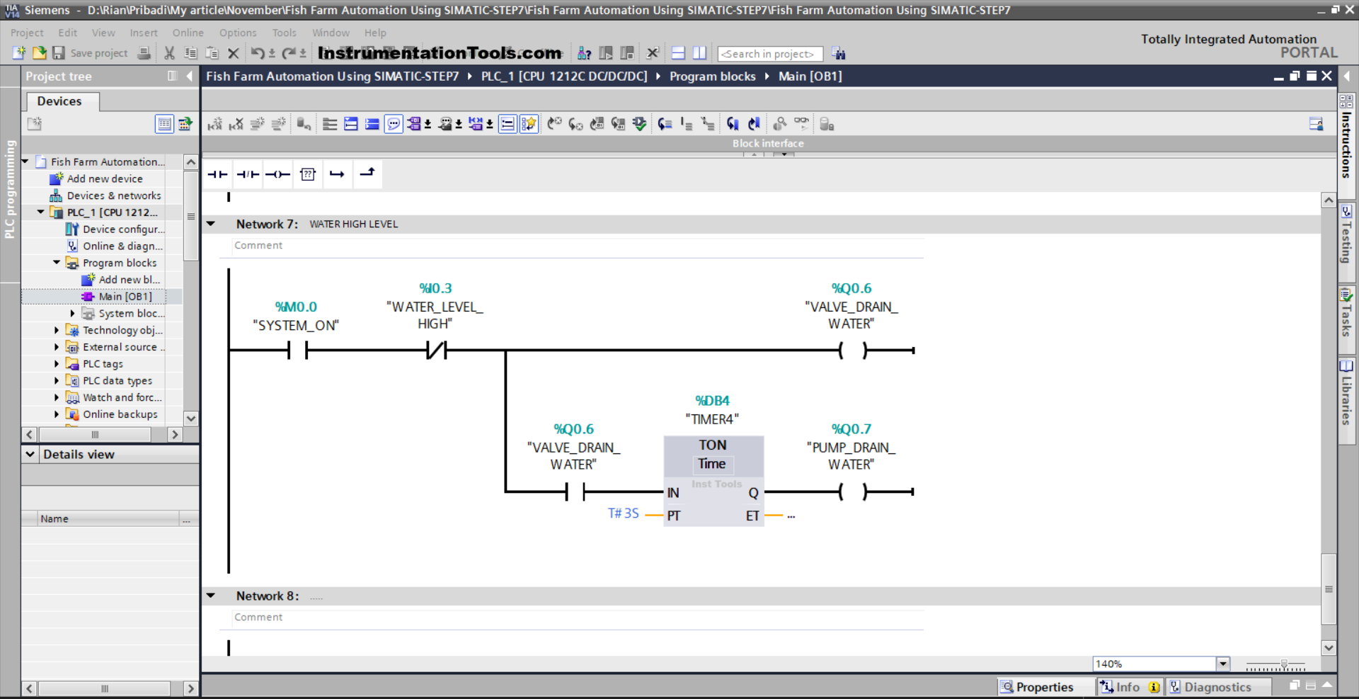
NETWORK 7 (WATER HIGH LEVEL)
In this Network, the output VALVE_DRAIN_WATER (Q0.6) will be OPEN when the NO contact of the memory bit SYSTEM_ON(M0.0) is in the HIGH state.
The timer TIMER4 (DB4) will start counting up to 3 seconds when the NO contact of the output VALVE_DRAIN_WATER (Q0.6) is in the HIGH state.
When the timer TIMER4 (DB4) has finished counting, the output PUMP_DRAIN_WATER (Q0.7) will become ON.
Read Next:
- PLC Program for Paper Cutting by Length and Count
- Siemens TIA Portal: Oven Control with Moving Conveyor
- XG5000 PLC Project: Continuous Liquid Tank Control Logic
- Paint Mixing System Control Program using Siemens PLC
- PLC Project for Dam Gate Control with 5 Alarm Levels