Inst ToolsInst ToolsInst Tools
  • Courses
  • Automation
    • PLC
    • Control System
    • Safety System
    • Communication
    • Fire & Gas System
  • Instrumentation
    • Design
    • Pressure
    • Temperature
    • Flow
    • Level
    • Vibration
    • Analyzer
    • Control Valve
    • Switch
    • Calibration
    • Erection & Commissioning
  • Interview
    • Instrumentation
    • Electrical
    • Electronics
    • Practical
  • Q&A
    • Instrumentation
    • Control System
    • Electrical
    • Electronics
    • Analog Electronics
    • Digital Electronics
    • Power Electronics
    • Microprocessor
Search
  • Books
  • Software
  • Projects
  • Process
  • Tools
  • Basics
  • Formula
  • Power Plant
  • Root Cause Analysis
  • Electrical Basics
  • Animation
  • Standards
  • 4-20 mA Course
  • Siemens PLC Course
Reading: Analyze the Relay Circuit and Find the Status ?
Share
Notification Show More
Font ResizerAa
Inst ToolsInst Tools
Font ResizerAa
  • Courses
  • Design
  • PLC
  • Interview
  • Control System
Search
  • Courses
  • Automation
    • PLC
    • Control System
    • Safety System
    • Communication
    • Fire & Gas System
  • Instrumentation
    • Design
    • Pressure
    • Temperature
    • Flow
    • Level
    • Vibration
    • Analyzer
    • Control Valve
    • Switch
    • Calibration
    • Erection & Commissioning
  • Interview
    • Instrumentation
    • Electrical
    • Electronics
    • Practical
  • Q&A
    • Instrumentation
    • Control System
    • Electrical
    • Electronics
    • Analog Electronics
    • Digital Electronics
    • Power Electronics
    • Microprocessor
Follow US
All rights reserved. Reproduction in whole or in part without written permission is prohibited.
Inst Tools > Blog > Practical Questions > Analyze the Relay Circuit and Find the Status ?

Analyze the Relay Circuit and Find the Status ?

Last updated: October 5, 2017 4:51 pm
Editorial Staff
Practical Questions
No Comments
Share
1 Min Read
SHARE

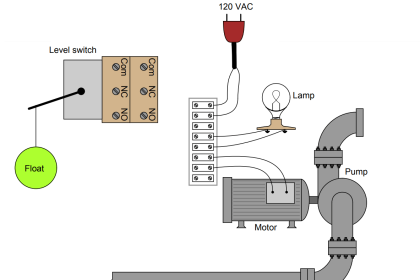
Determine the statuses of all lamps and relay coils in this circuit, given the following process conditions:
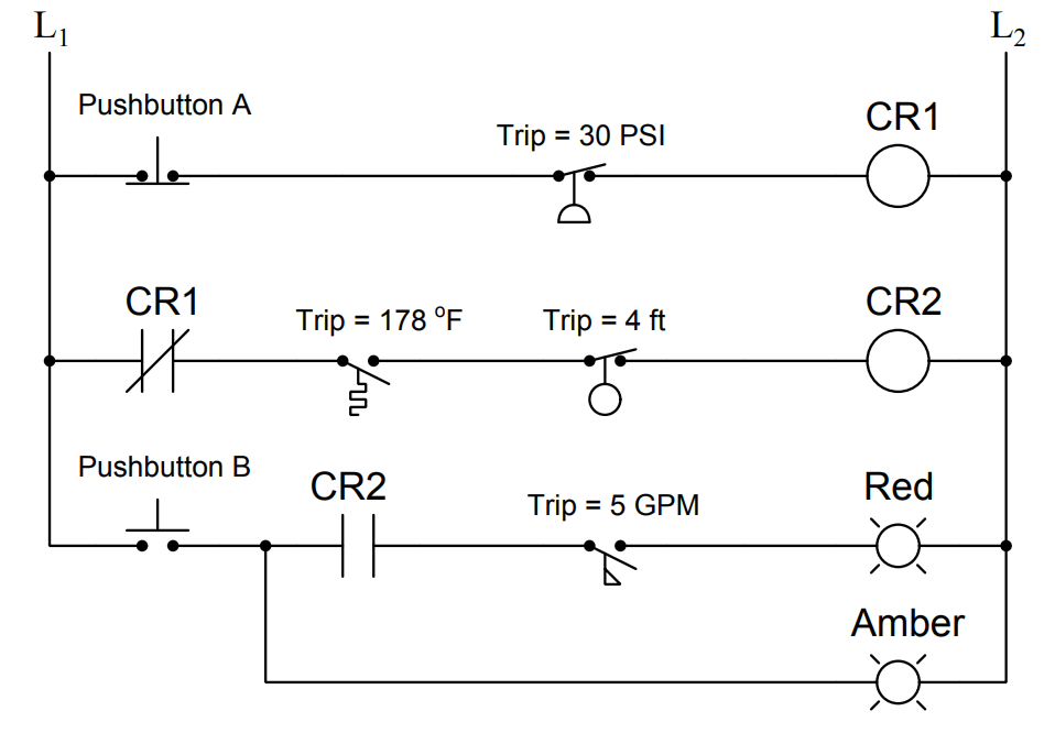
statuses of all lamps and relay coils in the circuit

  • Flow = 4 GPM
  • Pressure = 24 PSI
  • Temperature = 190 Deg F
  • Level = 2.5 ft
  • Pushbutton A = pressed
  • Pushbutton B = pressed

Answer :

Fully annotated circuit schematic: “X” representing an open contact or de-energized load, and “→” representing a closed contact or energized load.

statuses of all lamps and relay coils in the circuit - 2

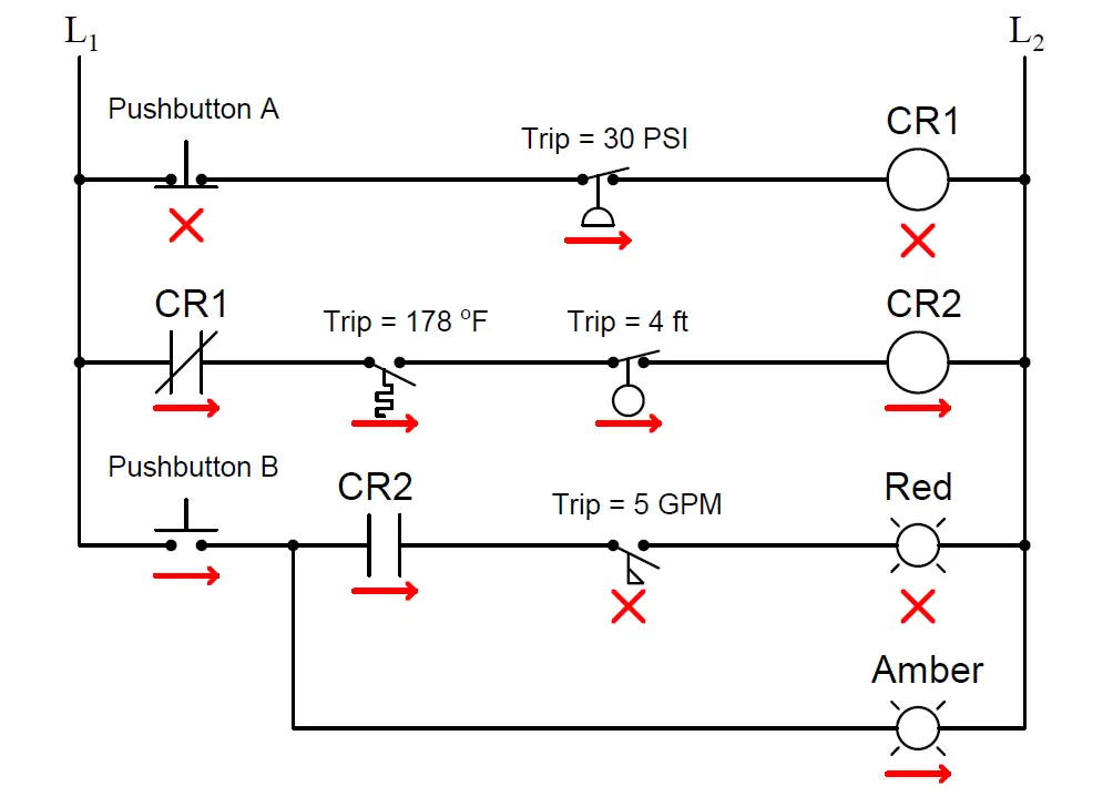
Recall that a process switch will be in its resting (“normal”) condition when the stimulus value is less than the trip threshold, and will be in its actuated condition when the stimulus exceeds the threshold.

Therefore,

  1. CR1 coil = de-energized
  2. CR2 coil = energized
  3. Red lamp = de-energized
  4. Amber lamp = energized

Share Your Answer / Comments

Credits : by Tony R. Kuphaldt – under CC BY 1.0

Don't Miss Our Updates
Be the first to get exclusive content straight to your email.
We promise not to spam you. You can unsubscribe at any time.
Invalid email address
You've successfully subscribed !

Continue Reading

Practical Process Control System Questions & Answers – 1
Questions on Pneumatic Transmitter and Repeater
What Effect on Hydrostatic Level Transmitter if Liquid Density Changes?
Calculate Density and Specific Gravity
How Manometer Measures Differential Pressure for Different Fluids?
How to Decrease Span of Pressure Gauge?
Share This Article
Facebook Whatsapp Whatsapp LinkedIn Copy Link
Share
Leave a Comment

Leave a Reply Cancel reply

Your email address will not be published. Required fields are marked *

Stay Connected

128.3kFollowersLike
69.1kFollowersFollow
210kSubscribersSubscribe
38kFollowersFollow

Categories

Explore More

Programmable Logic Controller (PLC) Questions and Answers – 6
Tank uses 3 Pressure Transmitters to Measure Level & Density
Galileo Thermometer
Calculate the Thermocouple’s Measurement Junction Temperature
Draw the appropriate Pressure Switch Symbol ?
Calculate Hydraulic System Fluid Pressure
Pneumatic Relay Questions
DP Transmitter Calibration Errors

Keep Learning

High and Low Ports on Pneumatic DP Transmitter

Identify High and Low Ports on Pneumatic DP Transmitter

Question on Remote Seal with Capillary Tubing Transmitter

Question on Remote Seal with Capillary Tubing Transmitter

Calculate Hydraulic Pressure of a Drum

Calculate Hydraulic Pressure of a Process Vessel

Calculate DPT Calibrated Range

Calculate the Transmitter Values

Two solenoid valves circuit

Solenoid Valves Questions & Answers – 4

Sump Tank Level Transmitter

Problem with Sump Tank Level Transmitter

Hydraulic Actuated Lift

Oil and Air Pressure Actuated Lifts Questions

solenoid valves trip

Identify Solenoid Valves Energized or de-energized?

Learn More

RTD Accuracy

What is RTD Accuracy ?

Point Gas Detectors Principle

Point IR Detectors Vs Open Path IR Detectors

RJ45 Connector Pins

How to make RJ45 cable

OPC Communication Interview Questions Answers

OPC Communication Interview Questions and Answers

HT motors Corrosion Problem

HT motors Corrosion Problem

Group of Induction Motors

How to Operate a Group of Induction Motors using PLC Logic?

Traces in TIA Portal

What is Trace Function in Tia Portal?

Electronics Projects

500 Electronics Projects for Engineering Students

Menu

  • About
  • Privacy Policy
  • Copyright

Quick Links

  • Learn PLC
  • Helping Hand
  • Part Time Job

YouTube Subscribe

Follow US
All rights reserved. Reproduction in whole or in part without written permission is prohibited.
Welcome Back!

Sign in to your account

Username or Email Address
Password

Lost your password?