This article explains the analog measurement in control system using ladder logic.
If measured value of revolution is 400 RPM/min, Calculate the equivalent voltage.

Here we need to measure both values. For physical quantity generally we use transducer. And here consider the range of transducer 0 to 10 V DC and the speed range can be calculated from 200 RPM/min to 1000 RPM/min.
So we will use standard conversion methods for it.
Here 0 V = 200 RPM/min
10 V DC = 1000 RPM/min
Then 10 V / 1000 V = 0.01 V/RPM/min
Now measured RPM is 400 RPM/min
so 400 RPM – 200 RPM x 0.01 RPM/min = 2 V.
Register and Memory :-
- Register A :- Actual voltage
- Register B :- Max RPM
- Register C :- Division value
- Register D :- Measured RPM
- Register E :- Min value of RPM
- Register F :- Calculated measured voltage
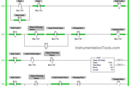
PLC Ladder Programming
NETWORK 1 :-

Division block is used for RPM conversion. Here we have calculated the RPM per voltage.
NETWORK 2 :-

RPM scale is starting from 200 to 1000 so start range value (200) is subtracted from the actual measured value (it is 400 RPM/min). And final value will be multiplied with the division (network 1).
Note:- Above application may be different from the actual application. This example is only for explanation and educational purpose only. We can implement this logic in other PLC also. This is the simple analog measurement using ladder logic, we can use this concept in other examples also.
All parameters and graphical representations considered in this example are for explanation purposes only, parameters or representation may be different in actual applications. Also all interlocks are not considered in the application.
If you liked this article, then please subscribe to our YouTube Channel for PLC and SCADA video tutorials.
You can also follow us on Facebook and Twitter to receive daily updates.
Read Next:
Ladder Logic for Sensor Scaling
Single Push button using Logic


Omron cp 1e input output electrical waring