Inst ToolsInst ToolsInst Tools
  • Courses
  • Automation
    • PLC
    • Control System
    • Safety System
    • Communication
    • Fire & Gas System
  • Instrumentation
    • Design
    • Pressure
    • Temperature
    • Flow
    • Level
    • Vibration
    • Analyzer
    • Control Valve
    • Switch
    • Calibration
    • Erection & Commissioning
  • Interview
    • Instrumentation
    • Electrical
    • Electronics
    • Practical
  • Q&A
    • Instrumentation
    • Control System
    • Electrical
    • Electronics
    • Analog Electronics
    • Digital Electronics
    • Power Electronics
    • Microprocessor
  • Request
Search
  • Books
  • Software
  • Projects
  • Process
  • Tools
  • Basics
  • Formula
  • Power Plant
  • Root Cause Analysis
  • Electrical Basics
  • Animation
  • Standards
  • 4-20 mA Course
  • Siemens PLC Course
Reading: Alarm Acknowledge using PLC
Share
Font ResizerAa
Inst ToolsInst Tools
Font ResizerAa
  • Courses
  • Design
  • PLC
  • Interview
  • Control System
Search
  • Courses
  • Automation
    • PLC
    • Control System
    • Safety System
    • Communication
    • Fire & Gas System
  • Instrumentation
    • Design
    • Pressure
    • Temperature
    • Flow
    • Level
    • Vibration
    • Analyzer
    • Control Valve
    • Switch
    • Calibration
    • Erection & Commissioning
  • Interview
    • Instrumentation
    • Electrical
    • Electronics
    • Practical
  • Q&A
    • Instrumentation
    • Control System
    • Electrical
    • Electronics
    • Analog Electronics
    • Digital Electronics
    • Power Electronics
    • Microprocessor
  • Request
Follow US
All rights reserved. Reproduction in whole or in part without written permission is prohibited.
Inst Tools > Blog > PLC Tutorials > Alarm Acknowledge using PLC

Alarm Acknowledge using PLC

Last updated: March 4, 2021 12:49 pm
Editorial Staff
PLC Tutorials
No Comments
Share
3 Min Read
SHARE

This article is about the PLC programming for the Alarm acknowledge logic.

Contents
ProblemAlarm Acknowledge using PLCLogic Description

In most industries, a standard procedure will be followed for alarm management. Some critical processes running in the industries may cause faults due to some failure of equipment, out-of-control process loops, etc.

Fault can be generated when some measured variable goes out of the range, this can be level, flow, temperature, pressure or any other kind of parameter.

Below discussed the example PLC program to acknowledge the alarms using Siemens TIA portal ladder logic.

Problem

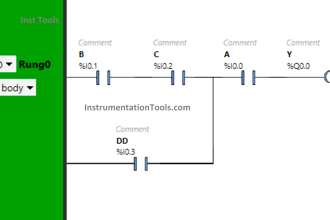
When there is a fault (I0.0) then alarm (Q0.0) should start blinking. When there is a fault signal, if the acknowledge button (I0.1) is pressed then the alarm will change from blinking to constant mode, means still there is a fault.

When the fault has gone, the alarm indication goes off.

Inputs

  1. FAULT (I0.0)
  2. ALARM ACKNOWLEDGE (I0.1)

Outputs

  1. ALARM INDICATION (Q0.0)

Alarm Acknowledge using PLC

Alarm Acknowledge using PLC Logic

Logic Description

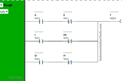
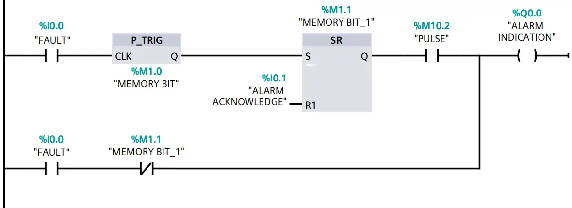
When the fault is generated, I0.0 becomes true, which allows the signal to pass through a positive edge detector which only allows the cycle to execute only once. After this signal goes to SR flip-flop where due to set has higher priority, the signal will be latched.

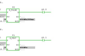
This signal will be passed through the clock pulse (M10.2 in our case), this generated the flashing alarm indicator.

 (note: here I have use bit M10.2 which is used to generate clock pulses.)

To select this bit, follow the step shown in the below figure.

Siemens CPU Clock Memory

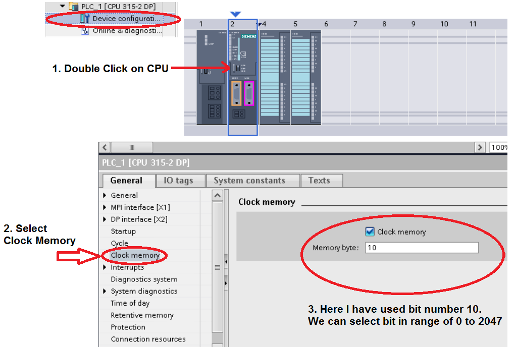
(another thing to note is that the number after decimal point indicate the rate of frequency, lower the number higher the frequency, like in our case after 10 there is 0.2 which indicate the rate of frequency or flashing rate like blinking LED.)

In the second rung, the Fault input status is in series with active memory bit of SR flip-flop (NC contact), which allows the signal to pass when the alarm is acknowledged. When the fault is normalized then the alarm indication goes off.

Author: Suhel Patel

If you liked this article, then please subscribe to our YouTube Channel for PLC and SCADA video tutorials.

You can also follow us on Facebook and Twitter to receive daily updates.

Read Next:

  • Problem on PLC, VFD, Motor
  • Connect to the Siemens S7 PLC
  • Instrument Percent of Span Error
  • Types of Interlocks
  • Analog and Digital Signals
Don't Miss Our Updates
Be the first to get exclusive content straight to your email.
We promise not to spam you. You can unsubscribe at any time.
Invalid email address
You've successfully subscribed !

Continue Reading

Siemens TIA Portal Free Version Download
PLC Motor Control Ladder Logic Programming
Analog Measurement using Ladder Logic
Proper Earthing Practices Used for PLC Control Panel
PLC Program for Mailbox with Letter Counting & Light Indicators
Control Loops Objective Questions and Answers
Share This Article
Facebook Whatsapp Whatsapp LinkedIn Copy Link
Share
Leave a Comment

Leave a Reply Cancel reply

Your email address will not be published. Required fields are marked *

Stay Connected

128.3kFollowersLike
69.1kFollowersFollow
210kSubscribersSubscribe
38kFollowersFollow

Categories

Explore More

What is Live Zero in 4-20 mA Current Loop?
Finding the Best PLC for Your Project – Tips and Tricks
Various Control Methods in Servo Motor Drives
Intrinsically Safe Barriers Questions and Answers
OFF Delay Timer using PLC
PLC Sequence Programming Ladder Logic
PLC Program for Two Way Switch Logic
PLC Functional Block Diagram for Logic Gates

Keep Learning

PLC Totalizer

PLC Program for Flow Totalizer

DCS Marshalling Cabinet Checks

PLC, DCS, and ESD Marshalling Cabinet Checks

PLC Program for Solenoid, Pilot Lamp, and Switch with Alarm

PLC Program for Solenoid, Pilot Lamp, and Switch with Alarm

PLC Program using Logic GATEs

PLC Logic GATE Program

Using Clock Memory Bits in TIA Portal - Siemens PLC

Using Clock Memory Bits in TIA Portal – Siemens PLC

Grounding Electronic Equipment

Importance of Grounding Electronic Equipment

What is meant by the Batching Process

Batch Simulator PLC Example Program using LogixPro Simulator

Create PLC Program based on Logic Circuit

Create PLC Program based on Logic Circuit

Learn More

Guide Wire Level Measurement

Float Level Measurement

Transformer voltage and turns ratio

Transformer Current Ratio

RAID stands for Redundant Array of Independent Disks

What is Raid Parity? – Types, Advantages, Disadvantages

Difference between DSP and DAC - Digital Electronics

Difference between DSP and DAC – Digital Electronics

Servo Level Transmitter Principle

Servo Level Transmitter Principle

Most Asked Questions on SCADA

Most Asked Questions on SCADA with Answers

Electrical bonding jumpers

Proper Sizing of Conductors

What is Barring Gear Logic? Why is it Required in the Steam Turbine?

Menu

  • About
  • Privacy Policy
  • Copyright

Quick Links

  • Learn PLC
  • Helping Hand
  • Part Time Job

YouTube Subscribe

Follow US
All rights reserved. Reproduction in whole or in part without written permission is prohibited.
Welcome Back!

Sign in to your account

Username or Email Address
Password

Lost your password?