Inst ToolsInst ToolsInst Tools
  • Courses
  • Videos
  • Q & A
    • Interview
      • Instrumentation
      • Electronics
      • Electrical
      • Practical Questions
    • MCQ
      • Instrumentation MCQ
      • Electrical MCQ
      • Electronics MCQ
      • Control Systems MCQ
      • Analog Electronics MCQ
      • Digital Electronics MCQ
      • Power Electronics MCQ
      • Microprocessor MCQ
      • Multiple Choice Questions
  • EE
    • Electronics
      • Electronics Q & A
      • Electronic Basics
      • Electronic Devices & Circuits
      • Electronics Animation
      • Digital Electronics
    • Electrical
      • Electrical Basics
      • Electrical Q & A
      • Power Electronics
      • Electrical Machines
      • Electrical Animation
      • Power Systems
      • Switchgear & Protection
      • Transmission & Distribution
  • Measure
    • Control Valves
    • Calibration
    • Temperature
    • Pressure
    • Flow
    • Level
    • Analyzers
    • Switches
    • Vibration
    • Solenoid Valve
  • Control
    • PLC Tutorials
    • Control Systems
    • Safety Instrumented System (SIS)
    • Communication
    • Fire & Gas System
  • More
    • Design
    • Tools
    • Animation
    • Basics
    • Formulas
    • Standards
    • TextBooks
    • Common
    • Software
    • Excel Tools
    • Erection & Commissioning
    • Process Fundamentals
    • Videos
    • Books
Search
All rights reserved. Reproduction in whole or in part without written permission is prohibited.
Reading: Ultrasonic Transmitters vs Guided Wave Radar for Level Measurement
Share
Notification Show More
Font ResizerAa
Inst ToolsInst Tools
Font ResizerAa
  • Courses
  • PLC Tutorials
  • Control Systems
Search
  • Courses
  • Videos
  • Q & A
    • Interview
    • MCQ
  • EE
    • Electronics
    • Electrical
  • Measure
    • Control Valves
    • Calibration
    • Temperature
    • Pressure
    • Flow
    • Level
    • Analyzers
    • Switches
    • Vibration
    • Solenoid Valve
  • Control
    • PLC Tutorials
    • Control Systems
    • Safety Instrumented System (SIS)
    • Communication
    • Fire & Gas System
  • More
    • Design
    • Tools
    • Animation
    • Basics
    • Formulas
    • Standards
    • TextBooks
    • Common
    • Software
    • Excel Tools
    • Erection & Commissioning
    • Process Fundamentals
    • Videos
    • Books
Follow US
All rights reserved. Reproduction in whole or in part without written permission is prohibited.
Inst Tools > Blog > Level Measurement > Ultrasonic Transmitters vs Guided Wave Radar for Level Measurement

Ultrasonic Transmitters vs Guided Wave Radar for Level Measurement

Last updated: July 12, 2019 3:39 pm
Editorial Staff
Level Measurement
No Comments
Share
7 Min Read
SHARE

ULTRASONIC TECHNOLOGY

Ultrasonic is a non-contact level measurement method that uses sound waves to determine the process material being measured.

Contents
ULTRASONIC TECHNOLOGYOther problematic aspects of Ultrasonic transmitters to consider include:Vacuum ApplicationsSurface ConditionAnglesIrregularitiesTemperature LimitsPressure LimitsEnvironmental ConditionsGUIDED WAVE RADAR (GWR) TECHNOLOGYGWR is suitable for a variety of level measurement applications including:Unstable Process ConditionsAgitated SurfacesExtreme Operating limitsFine Powders & Sticky FluidsThe chart below compares some important features between Ultrasonic and Guided Wave Radar

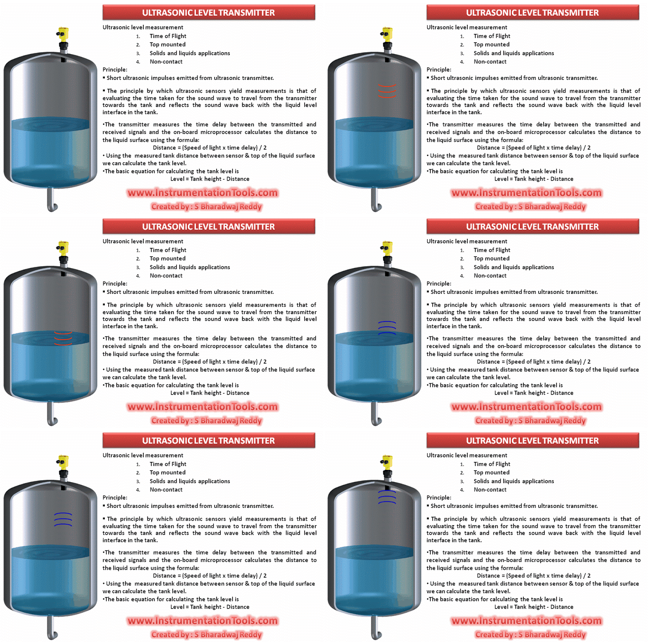
Ultrasonic transmitters operate by sending a sound wave, generated from a piezo electric transducer, to the media being measured. The device measures the length of time it takes for the reflected sound wave to return to the transducer.

A successful measurement depends on reflection from the process material in a straight line back to the transducer.

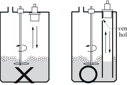
However, there are various influences that affect the return signal. Factors such as dust, heavy vapors, tank obstructions, surface turbulence, foam and even surface angles can affect the returning signal.

That is why the conditions that determine the characteristics of sound must be considered when using Ultrasonic measurement.

Other problematic aspects of Ultrasonic transmitters to consider include:

Vacuum Applications

  • Sound must travel through a medium (usually air)
  • The absence of air molecules prevents the propagation of sound waves

Surface Condition

Angles

  • Sound waves must be sent and received in a straight line
  • Reflective surfaces must be flat (i.e. Non-agitated/Non-turbulent condition)

Irregularities

  • Foam and other debris collected on the surface of the liquid which absorbs the sound waves and impedes their return sound travel to the sensor

Temperature Limits

  • Ultrasonic units are typically plastic with a maximum temperature of 140˚F (60˚C)
  • Varying process temperatures may generate inaccurate readings

Pressure Limits

  • Ultrasonic devices are not intended for extreme pressure limits
  • Maximum working pressures should not exceed of 30 PSIG (2 Bar)

Environmental Conditions

  • Ultrasonic devices should be mounted in a predictable environment
  • Vapor, condensing humidity, and other contaminates that change the speed of sound through air greatly effect the accuracy of the return signal

Also Read: Ultrasonic Level Transmitter Working Animation

The most popular benefit  of through-air measurement  principles like Ultrasonic, Radar, or Laser measurement is the fact that the measuring signal never comes in contact with the product being measured. But if you think about  it, this ‘fact’ is not entirely accurate. Take Ultrasonics for example: When sound energy leaves the transducer, it travels through  air at 1,125  feet per second until it reaches its target (i.e. liquid surface).

Similar to all other “non-contacting” type of level measurement, at some point the measuring signal must come in contact with the liquid surface before it begins its return trip back to the sensor. This not only explains why the air quality between the sensor and liquid surface can be problematic, but also why the quality of the liquid surface needs to be accounted for. Every disturbance it picks up on its way down and back will disturb the actual level measurement information in the signal

It is important to understand that Ultrasonic transmitters will provide a sensible solution, when properly applied. Remember, the Ultrasonic transmitter is just as good as the echo it receives.

GUIDED WAVE RADAR (GWR) TECHNOLOGY

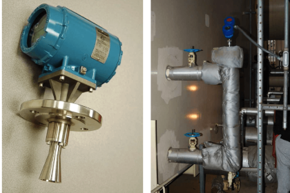
Guided Wave Radar (GWR) is a contacting level measurement method that uses a probe to guide high frequency, electromagnetic waves as they travel down from a transmitter to the media  being  measured.

GWR is based upon the principle of Time Domain  Reflectometry (TDR), which is an electrical measurement technique that has been used for several decades in various industrial measurement applications; among its first fields of application was the location of cable damage. In level measurement, however, TDR has only been used for a little over a decade.

With TDR, a low-energy electromagnetic pulse is guided along a probe. When the pulse reaches the surface of the medium being measured, the pulse  energy is reflected up the probe  to the circuitry which then  calculates the fluid level from the time difference between the pulse  sent  and the pulse  reflected. The sensor can output the analyzed level as a continuous measurement reading through its analog output, or it can convert the values into freely positionable switching output signals.

GWR is suitable for a variety of level measurement applications including:

Unstable Process Conditions

  • Changes in viscosity, density, or acidity do not effect accuracy

Agitated Surfaces

  • Boiling surfaces, dust, foam, vapor do not effect device performance
  • Recirculating fluids, propeller mixers, aeration  tanks

Extreme Operating limits

  • GWR performs well under extreme  temperatures up to 600ºF (315ºC)
  • Capable  of withstanding  pressures up to 580 PSIG (40 Bar)

Fine Powders & Sticky Fluids

  • Vacuum tanks with used cooking oil
  • Paint, latex, animal fat and soy bean oil
  • Saw dust, carbon black, titanium tetrachloride, salt, grain

Also Read: Guided Wave Radar Level Transmitter Working Animation

One of the most common misconceptions of GWR is the effects of product build-up on the probe.  One would think that if you have a mass of product stuck to the probe, or a coating of product throughout the entire probe length, that the signal would misidentify the true liquid surface.

This in fact is not the case with advanced GWR technology. The radar signal of GWR has a very large detection area around the probe covering 360˚ of area over several feet of coverage.  When this pulse energy comes in contact with a mass of product on the probe, the signal is returned and analyzed to see if it is the true liquid level.

Since the liquid level always has a larger signal return than the smaller mass that is sticking on the probe, the liquid surface is easily identifiable. The advanced algorithms developed over the last decade have made this contacting form of level measurement the ideal solution  for even  the stickiest of fluid applications.

Advantages of GWR in the level industry are endless.  Unlike older technologies, GWR offers measurement readings that are independent of chemical or physical properties found in the contact media. Additionally, GWR performs equally well in liquids and solids.

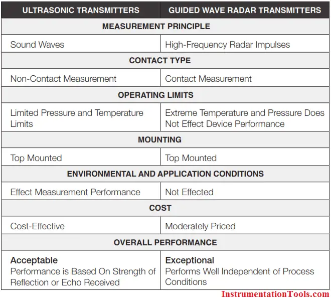
The chart below compares some important features between Ultrasonic and Guided Wave Radar

Ultrasonic Transmitters versus Guided Wave Radar Transmitters

Also Read: Zero Suppression & Zero Elevation in Level Measurement
Don't Miss Our Updates
Be the first to get exclusive content straight to your email.
We promise not to spam you. You can unsubscribe at any time.
Invalid email address
You've successfully subscribed !

Continue Reading

Comparison of Level Meters – Level Measurement Instruments
Micro-impulse Level Transmitter Principle
Displacer Level Transmitter 5-point Calibration
Differential Pressure Transmitters Compensated Leg Systems
Laser Level Measurement Principle
Displacer (buoyancy) Level Transmitter Principle, Limitations, Design, Installation & Calibration
Share This Article
Facebook Whatsapp Whatsapp LinkedIn Copy Link
Share
Leave a Comment

Leave a Reply Cancel reply

Your email address will not be published. Required fields are marked *

Stay Connected

128.3kFollowersLike
69.1kFollowersFollow
208kSubscribersSubscribe
38kFollowersFollow

Categories

Explore More

What is a Level Switch? Types of Level Switches
Closed Tank Remote Seal Capillary type DP Transmitter
DP Level Transmitter Auto Calibration
Probe Type GWR Level Transmitter Working Animation
What is Reflex Level Gauge?
Level Transmitter Calibration Procedure
Closed tank DP Level Transmitter with cleaning leg Calibration
Level Instruments General Specifications
Bubbler Liquid Level Transmitter Calculation
How to do Interface Level Calculation using DP Transmitter ?

Keep Learning

Hydrostatic interface level measurement Formula

Hydrostatic Interface Level Measurement

Displacer Level Sensor Working Animation

Displacer Level Sensor Working Animation

DP-Level-Measurement-Calculation-Below-Tapping-Point-Open-Tank

Differential Pressure (DP) Level transmitter Installed Below Tapping Point

Dip Tape

What is Dip Tape Level Measurement?

Displacer Level Transmitter weight calibration

Displacer Level Transmitter Dry Calibration with Weights

Differential Pressure Measurement

Basics of Differential Pressure Level Transmitters

Level Transmitter with Zero Suppression

DP Level Transmitters Compensation Techniques

Submersible Pressure Transmitter

What is a Submersible Pressure Transmitter? Principle, Advantages

Discover More

Chemical Battery

Batteries

Practical Control Systems Questions & Answers

Practical Process Control System Questions & Answers – 1

Thermography and Thermometry Objective Questions

Thermography and Thermometry Objective Questions

Phase Controlled Half Wave Rectifier RL Load

Power Electronics – Phase Controlled Half Wave Rectifier RL Load

What is a Dosing Pump? - Types, Advantages, Applications

What is a Dosing Pump? – Types, Advantages, Applications

Introduction of Urea Bagging machine

Introduction to Urea Bagging Machine

Hydraulic versus Pneumatic Systems

Hydraulic versus Pneumatic Systems

Selection of Fire and Gas Detectors

Basic Guidelines for Selection of Fire and Gas Detectors

Follow US
All rights reserved. Reproduction in whole or in part without written permission is prohibited.
Welcome Back!

Sign in to your account

Username or Email Address
Password

Lost your password?