Inst ToolsInst ToolsInst Tools
  • Courses
  • Automation
    • PLC
    • Control System
    • Safety System
    • Communication
    • Fire & Gas System
  • Instrumentation
    • Design
    • Pressure
    • Temperature
    • Flow
    • Level
    • Vibration
    • Analyzer
    • Control Valve
    • Switch
    • Calibration
    • Erection & Commissioning
  • Interview
    • Instrumentation
    • Electrical
    • Electronics
    • Practical
  • Q&A
    • Instrumentation
    • Control System
    • Electrical
    • Electronics
    • Analog Electronics
    • Digital Electronics
    • Power Electronics
    • Microprocessor
Search
  • Books
  • Software
  • Projects
  • Process
  • Tools
  • Basics
  • Formula
  • Power Plant
  • Root Cause Analysis
  • Electrical Basics
  • Animation
  • Standards
  • 4-20 mA Course
  • Siemens PLC Course
Reading: Contact Type Guided Wave Radar Level Transmitter Working Principle
Share
Notification Show More
Font ResizerAa
Inst ToolsInst Tools
Font ResizerAa
  • Courses
  • Design
  • PLC
  • Interview
  • Control System
Search
  • Courses
  • Automation
    • PLC
    • Control System
    • Safety System
    • Communication
    • Fire & Gas System
  • Instrumentation
    • Design
    • Pressure
    • Temperature
    • Flow
    • Level
    • Vibration
    • Analyzer
    • Control Valve
    • Switch
    • Calibration
    • Erection & Commissioning
  • Interview
    • Instrumentation
    • Electrical
    • Electronics
    • Practical
  • Q&A
    • Instrumentation
    • Control System
    • Electrical
    • Electronics
    • Analog Electronics
    • Digital Electronics
    • Power Electronics
    • Microprocessor
Follow US
All rights reserved. Reproduction in whole or in part without written permission is prohibited.
Inst Tools > Blog > Level Measurement > Contact Type Guided Wave Radar Level Transmitter Working Principle

Contact Type Guided Wave Radar Level Transmitter Working Principle

Last updated: September 14, 2016 6:25 pm
Editorial Staff
Level Measurement
No Comments
Share
5 Min Read
SHARE

Guided wave radar (GWR) is also called time domain reflectometry (TDR) or micro-impulse radar (MIR).

Basic principle

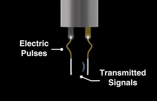
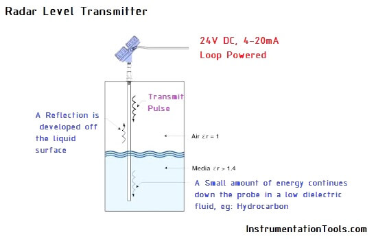
In a Guided Wave Radar installation, the GWR is mounted on the top of the tank or chamber, and the probe usually extends to the full depth of the vessel. A low energy pulse of microwaves, travelling at the speed of light, is sent down the probe. At the point of the liquid level (air / water interface) on the probe, a significant proportion of the microwave energy is reflected back up the probe to the transmitter.

Probe Type Radar Level Transmitter

The transmitter measures the time delay between the transmitted and received echo signal and the on- board microprocessor calculates the distance to the liquid surface using the formula:

Distance = (Speed of light x time delay) / 2

Once the transmitter is programmed with the reference gauge height of the application – usually the bottom of the tank or chamber – the liquid level is calculated by the microprocessor.

The basic equation for measuring the tank level is

Level = Tank Height – Distance

Because a proportion of the pulse will continue down the probe through low dielectric fluids, a second echo can be detected from an interface between two liquids at a point below the initial liquid level.

This characteristic makes guided wave radar a good technique for measuring liquid/liquid interfaces such as oil and water and measuring through some foams.

Guided wave radar can be used in vessels with tight geometry, in chambers, and in tanks of all sizes. Advanced GWR also works well in low dielectric and turbulent applications. Because it is not dependent on reflecting off a “flat” surface, it works well with many powders and grains as well as liquids with slanted surfaces caused by vortices.

Guided wave radar technology Benefits

  1. No moving parts and no re-calibration minimizes maintenance
  2. Direct level measurement means no compensation needed for changing process conditions (i.e. density, conductivity, temperature, and pressure)
  3. Handles vapor and turbulence well
  4. Suitable for small tanks, difficult tank geometry, and interfering obstacles
  5. Allows for easy upgrade
  6. Top down installation minimizes risk for leakages

Advantages

  1. Guided wave radar (GWR) provides an accurate and reliable measurement for both level and interface, and can be used in a wide variety of applications.
  2. It is a top-down, direct measurement as it measures the distance to the surface.
  3. GWR can be used with liquids, sludges, slurries, and some solids.
  4. A key advantage of radar is that no compensation is necessary for changes in the density, dielectric, or conductivity of the fluid.
  5. Changes in pressure, temperature, and most vapor space conditions have no impact on the accuracy of radar measurements.
  6. In addition, radar devices have no moving parts
  7. So maintenance is minimal. GWR is easy to install and can easily replace other technologies, such as displacer and capacitance, even while there is liquid in the tank.

Limitations

While guided wave radar works in many conditions, some precautions need to be taken with respect to probe choice. Several probe styles are available and the application, length, and mounting restrictions influence their choice. Unless a coax-style probe is used, probes should not be in direct contact with a metallic object, as that will impact the signal. If the application tends to be sticky or coat, then only single lead probes should be used. Some advanced GWRs on the market have advanced diagnostics, with the ability to detect build-up on the probe. Chambers with a diameter less than 3 in. (75 mm) may cause problems with build-up and may make it difficult to avoid contact between chamber wall and probe.

Don't Miss Our Updates
Be the first to get exclusive content straight to your email.
We promise not to spam you. You can unsubscribe at any time.
Invalid email address
You've successfully subscribed !

Continue Reading

Level Instruments General Specifications
Closed Tank Level Measurement using DP Transmitters
Non-Contacting Radar Level Transmitter Working Principle
DP Transmitter Dry Leg & Wet Leg Calculations
Basics of Differential Pressure Level Transmitters
Level Gauge Interface & Temperature Problems
Share This Article
Facebook Whatsapp Whatsapp LinkedIn Copy Link
Share
Leave a Comment

Leave a Reply Cancel reply

Your email address will not be published. Required fields are marked *

Stay Connected

128.3kFollowersLike
69.1kFollowersFollow
210kSubscribersSubscribe
38kFollowersFollow

Categories

Explore More

Magnetic Level Indicators Working Animation
Torque Tube Level Measurement Principle
Float Type Level Indicator Principle
Magnetic Float Level Transmitter Working Principle
What is Reflex Level Gauge?
How Tilt Level Switch Works ?
Micro-impulse Level Transmitter Principle
Types of Level Gauges

Keep Learning

Level Transmitters Auto Calibration

DP Level Transmitter Auto Calibration

capacitance probe

Capacitance Level Measurement Working Principle

Calibrating Transmitter System One Seal with suppressed Zero

Calibrating Level Transmitter with Remote Seals

Magnetostrictive Level Transmitter Working Principle

Magnetostrictive Level Transmitter Working Principle

Zero Suppression in level Measurement

Zero Suppression and Zero Elevation Calculations

Comparison of Level Meters - Level Measurement Instruments

Comparison of Level Meters – Level Measurement Instruments

Wet Leg Level Transmitter

Basics of DP Level Measurement

Boiler Level Switch

Float level switch Principle

Learn More

What is a Wet Contact in PLC

What is a Wet Contact? – Basics of PLC Wiring

Level Transmitter Design

Level Transmitter and Level Gauge Design Tips

Valve Diaphragm Actuator

Spring and Diaphragm Pneumatic Actuators

Magnetic Tape Recorder Principle

What is Magnetic Tape Recorder ?

car parking example logic

Up Down Counter Instruction in PLC

Current to percentage conversion

Convert current (4-20mA) to Percentage (0-100%)

Centrifugal Compressor outage reduced

Centrifugal Compressor Outage Reduced – Root Cause Analysis

3-way-2-position-solenoid-valve-spring-return

Pneumatic Directional Control Valves

Menu

  • About
  • Privacy Policy
  • Copyright

Quick Links

  • Learn PLC
  • Helping Hand
  • Part Time Job

YouTube Subscribe

Follow US
All rights reserved. Reproduction in whole or in part without written permission is prohibited.
Welcome Back!

Sign in to your account

Username or Email Address
Password

Lost your password?