This article discusses how to build OPC UA communication between two S7-1500 PLCs in TIA Portal V18, where one CPU acts as an OPC UA Server and the other CPU as an OPC UA Client, complete with testing in PLCSIM Advanced. OPC UA is a vendor-independent industrial communication protocol, so a PLC can provide its data to SCADA, HMI, or another PLC, and can also read and write data from other servers. Unlike PUT/GET, which uses memory addresses, OPC UA accesses data through variable names published by the server, so it is more flexible and not tied to absolute addresses.
Siemens PLC as an OPC UA Server and Client
The system built consists of two 1513-1 PN CPUs. PLC_1 (IP 192.168.0.1, port 4840) acts as the OPC UA Server that provides variables inside DB_OPC_Server. PLC_2 (IP 192.168.0.2) acts as the OPC UA Client that reads and writes data to PLC_1 using the compact blocks OPC_UA_ReadList_C and OPC_UA_WriteList_C, triggered periodically by the 1 Hz clock memory.
PLC_2 reads the actual status and speed from the server, then writes the start command and speed setpoint to the server. The whole flow is built without touching memory addresses and tested with two PLCSIM Advanced instances.
Prerequisites
- The reader already knows how to add a CPU and set the IP address in TIA Portal.
- The reader already understands how to create a Data Block and drag instructions into OB1.
- The reader already knows how to run a virtual CPU with PLCSIM Advanced and create a Watch table.
OPC UA Concept on the S7-1500
In OPC UA, one device acts as a server and another device as a client. The server provides variables in an address space that can be browsed, while the client opens a session to the server, then reads or writes those variables. The S7-1500 CPU can act as a server or a client, but both must be enabled in the CPU properties and require the appropriate OPC UA license type. The server address is written as an endpoint, for example, opc.tcp://192.168.0.1:4840, with 4840 as the standard port.
On the server side, TIA Portal provides the Standard SIMATIC server interface. With this option active, DB variables that are given OPC UA access permission are immediately available to the client without creating a server interface file manually. This also avoids a crash that can occur during compilation if a self-made server interface is added in TIA Portal V18.
On the client side, the required variables are grouped in a read list and a write list in the client interface. TIA Portal creates Data Blocks for the configuration and the data of those lists, and the compact blocks OPC_UA_ReadList_C and OPC_UA_WriteList_C perform the reading and writing. Each command is triggered by the REQ signal, which in this article comes from the 1 Hz clock memory.
PLCSIM Advanced supports OPC UA only through the TCP/IP communication mode with the PLCSIM Virtual Eth. Adapter, so port 4840 can be accessed between instances. The server must also already be running before the client is configured, because the client selects variables by browsing the address space of the server that is online.
Project and Simulation Network Preparation
Step 1: Preparing the Project and Two PLCSIM Advanced Instances
- Create a new project in TIA Portal. Right-click the project name in the Project tree, select Properties > Protection, then check Support simulation during block compilation.
- Add two S7-1500 CPUs, for example, CPU 1513-1 PN with firmware V2.9 or V3.0.
- PLC_1 (Server): Set the IP to 192.168.0.1 and the subnet mask to 255.255.255.0.
- PLC_2 (Client): Set the IP to 192.168.0.2 and the subnet mask to 255.255.255.0.
- Open Devices & networks > Network view, then drag a connection line between the PROFINET port X1 on PLC_1 and PLC_2 so that both are on one subnet PN/IE_1.
- Open S7-PLCSIM Advanced Control Panel, then change Online Access to PLCSIM Virtual Eth. Adapter. This TCP/IP mode is required so that the OPC UA port 4840 can be accessed.
- Create and run two virtual instances: PLC_1 (192.168.0.1) and PLC_2 (192.168.0.2).
- Verification: both instances appear active in the Active PLC Instances list in PLCSIM Advanced with the TCP/IP network indicator.
OPC UA Server Tutorial (PLC_1)
Step 2: Enabling the OPC UA Server and Download
- Open the Device configuration of PLC_1, then open Properties > General > OPC UA > Server > General and check Activate OPC UA server.
- Open OPC UA > Server > Export, then make sure the Standard SIMATIC server interface option is checked. With this option, you do not need to create a server interface file manually in the Project tree.
- Open OPC UA > Server > Security. Under Secure channel (Security policies), check No security. Under User authentication, check Guest authentication.
- Scroll to Runtime licenses > OPC UA, then select SIMATIC OPC UA S7-1500 small in the Type of purchased license column.
- Create a Global Data Block DB_OPC_Server on PLC_1 with the following variables. Make sure the Accessible from HMI/OPC UA and Writable from HMI/OPC UA columns are checked for all of them.
- Server_Status_Run (Bool), which will be read by PLC_2.
- Server_Actual_Speed (Int), which will be read by PLC_2.
- Client_Cmd_Start (Bool), which will be written by PLC_2.
- Client_Speed_SP (Int), which will be written by PLC_2.
- Right-click PLC_1 > Compile > Hardware and software (rebuild all), then Download to device via the PLCSIM Virtual Ethernet Adapter interface and change the CPU mode to RUN.
- Verification: the compile and download of PLC_1 finish with 0 errors, and the PLC_1 indicator in PLCSIM Advanced lights up green (RUN).
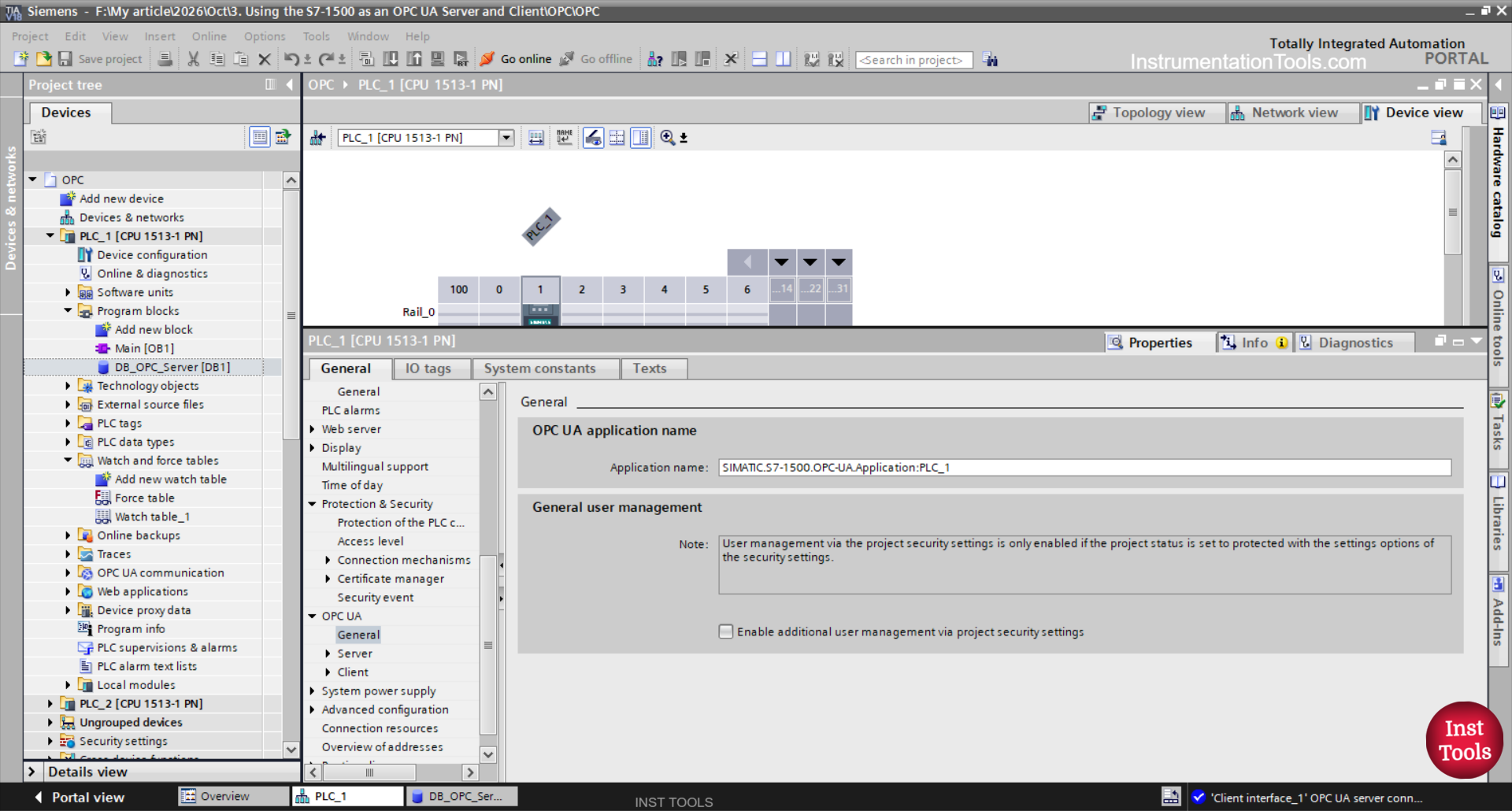
How does the server configuration work?
By enabling the OPC UA server, PLC_1 opens port 4840 and provides the address space. Because the Standard SIMATIC server interface is active, every variable given OPC UA access permission in DB_Server automatically appears in the address space, without having to build an interface yourself.
The No security and Guest authentication settings allow the client to connect without a certificate and account, so they suit simulation. The Writable permission is given to variables that the client may change, namely Client_Cmd_Start and Client_Speed_SP.
OPC UA Client Tutorial (PLC_2)
Step 3: Enabling the OPC UA Client and Clock Memory
- Open the Device configuration of PLC_2, then open Properties > General > OPC UA > Client and check Activate OPC UA client.
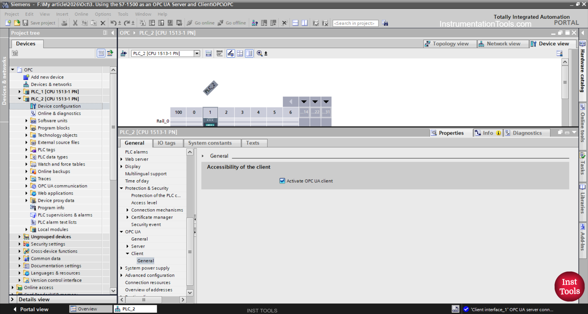
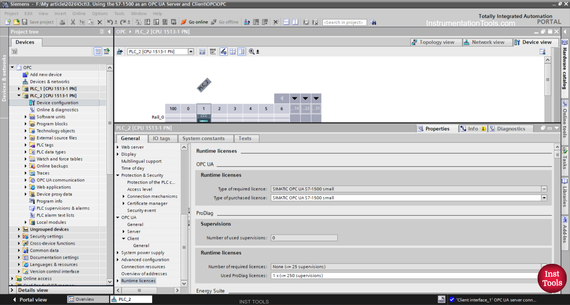
- Scroll to Runtime licenses > OPC UA, then select SIMATIC OPC UA S7-1500 small.
- Open System and clock memory in the properties of PLC_2, then check Enable the use of clock memory byte. By default, this byte is %MB0, and bit %M0.5 produces a 1 Hz pulse that is used to trigger the reading and writing of data periodically.
Step 4: Creating the Client Interface with Read List and Write List
- In the PLC_2 Project tree, expand OPC UA communication > Client interfaces, then double-click Add new client interface so that Client interface_1 is formed.
- Click Client interface_1 and open the Properties window at the bottom. Under General > Connection parameter, fill Address with 192.168.0.1 (the IP of PLC_1) and Port with 4840.
- Under Security, set Security mode to No security and User authentication to Guest.
- In the right panel of the editor (OPC UA server interface), change the Source dropdown from Imported interface to Online, then click Online access.
- In the pop-up window, click Find selected server (opc.tcp://192.168.0.1:4840), select the endpoint None (No security), then click Connect.
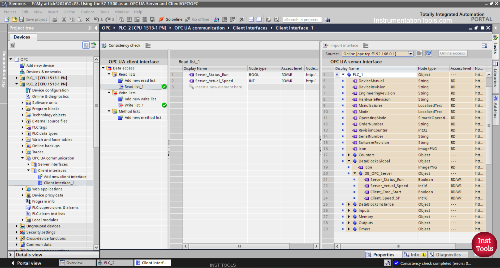
- After the PLC_1 variable tree appears in the right panel (PLC_1 > DataBlocksGlobal > DB_OPC_Server), map the read and write lists in the left panel.
- Read list: double-click Add new read list under Read lists (ReadList_1 is formed). Drag the variables Server_Status_Run and Server_Actual_Speed from the right panel to the middle table (Data access).
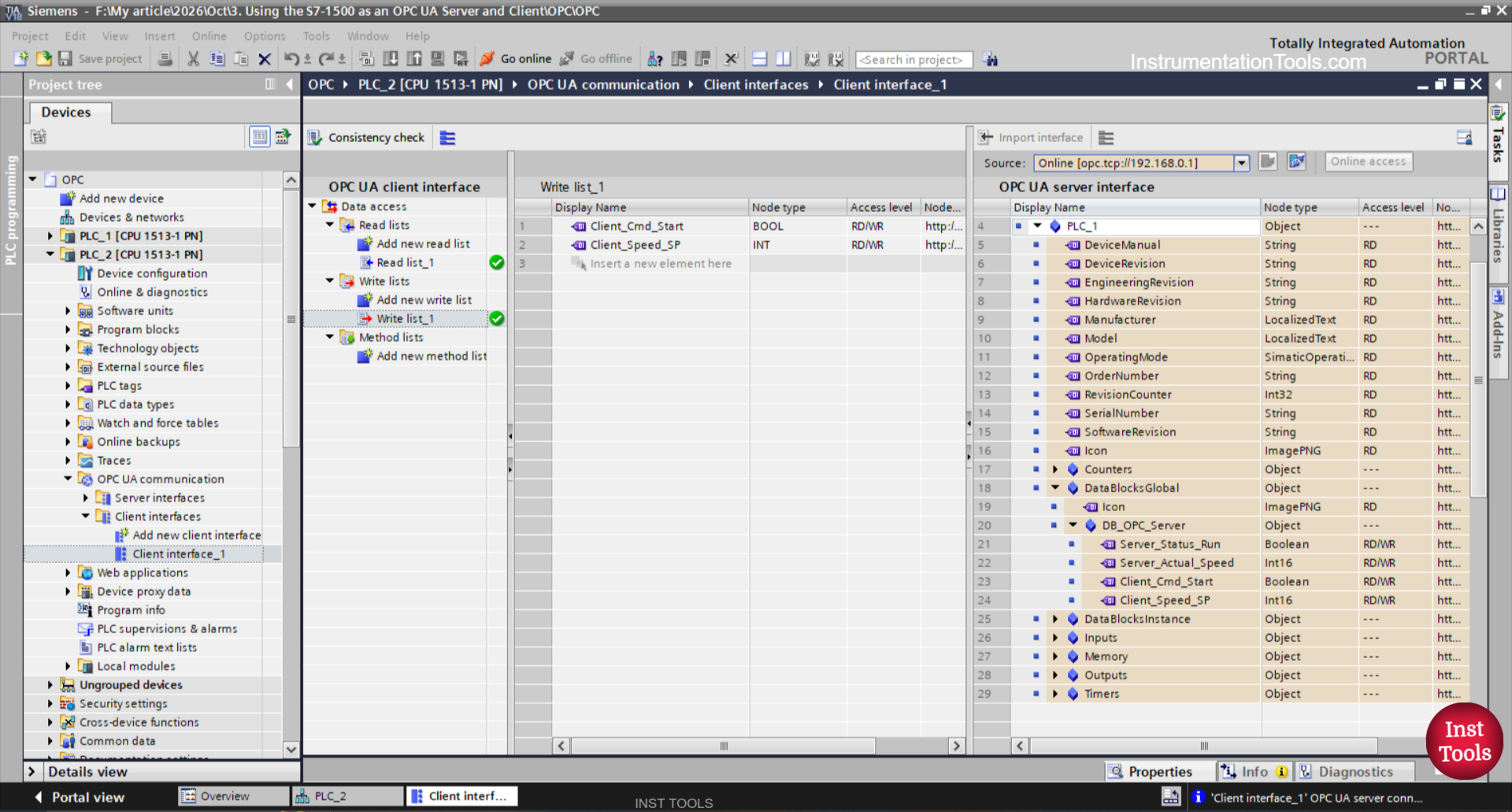
- Write list: double-click Add new write list under Write lists (WriteList_1 is formed). Drag the variables Client_Cmd_Start and Client_Speed_SP from the right panel to the middle table (Data access).
- Click the Consistency check icon at the top of the left panel.
- Verification: the consistency check shows a green status, and TIA Portal automatically generates the data blocks Client interface_1_Configuration and Client interface_1_Data under the OPC UA communication folder of PLC_2.
How does the client configuration work?
The address and port in the Connection parameter determine which server to contact, while the security settings must be the same as the server (No security and Guest). With the Online source, TIA Portal browses the address space of the running PLC_1, so the selected variables are guaranteed to exist on the server.
The read list contains the variables to be read from the server, and the write list contains the variables to be written to the server. When the consistency check passes, TIA Portal creates Client interface_1_Configuration to store the session configuration and Client interface_1_Data to store the read values and the values to be written.
Step 5: Creating the Communication Program in OB1 of PLC_2
- Open Main [OB1] in the Program blocks of PLC_2.
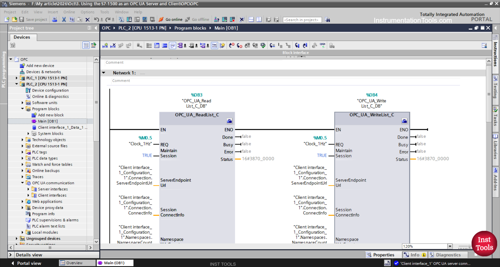
- From the Instructions > Communication > OPC UA > OPC UA Client panel, drag OPC_UA_ReadList_C to Network 1 and OPC_UA_WriteList_C to Network 1. Accept the creation of the instance DBs for both.
- Configure OPC_UA_ReadList_C (Network 1): click the blue toolbox icon (Start configuration) above the block. Select Client interface: Client interface_1 and Data access: ReadList_1, so the lower parameter pins are filled in automatically. Fill the MaintainSession input pin with TRUE and REQ with “Clock_1Hz” (%M0.5).
- Configure OPC_UA_WriteList_C (Network 2): click the blue toolbox icon above the block. Select Client interface: Client interface_1 and Data access: WriteList_1. Fill the MaintainSession input pin with TRUE and REQ with “Clock_1Hz” (%M0.5).
- Right-click PLC_2 > Compile > Hardware and software (rebuild all), then Download to device to the PLC_2 instance (192.168.0.2) and make sure the CPU status is RUN.
- Verification: both blocks, when monitored online, have a green border with the Error output = FALSE.
How does the OB1 program work?
The client program consists of only two blocks. OPC_UA_ReadList_C reads the entire contents of ReadList_1 from the server, and OPC_UA_WriteList_C writes the entire contents of WriteList_1 to the server. Both blocks are triggered by REQ connected to Clock_1Hz (%M0.5), so every second a rising edge occurs that starts one read cycle and one write cycle.
MaintainSession with the value TRUE keeps the session to the server open, so the next request does not need to open a new session. The read results are stored in Client interface_1_Data, and the values written are taken from the same data. The blocks take care of opening the session and sending the requests, so the program needs no additional code.
Testing with PLCSIM Advanced
Step 6: Testing Two-Way Reading and Writing
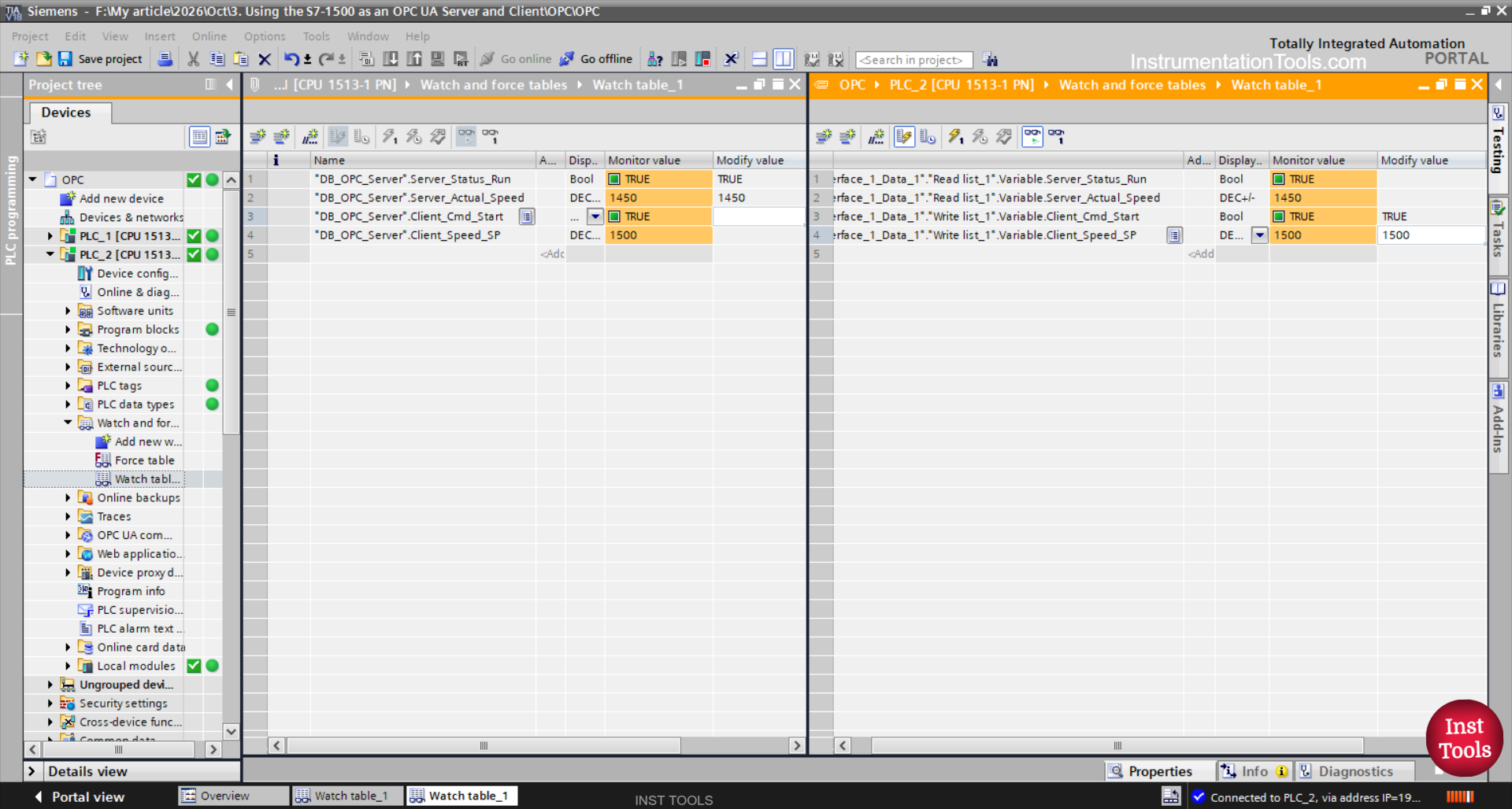
- Create a Watch table on PLC_1 (containing the DB_OPC_Server variables) and on PLC_2 (containing the variables inside Client interface_1_Data). Enable Monitor All on both.
- Reading test (PLC_1 Server to PLC_2 Client): In the PLC_1 Watch table, change “DB_OPC_Server”.Server_Status_Run to TRUE and “DB_OPC_Server”.Server_Actual_Speed to 1450.
- Observe the PLC_2 Watch table. Within a maximum of 1 second (the %M0.5 cycle), “Client interface_1_Data”.ReadList_1.Variable.Server_Status_Run changes to TRUE and Server_Actual_Speed to 1450.
- Writing test (PLC_2 Client to PLC_1 Server): In the PLC_2 Watch table, change “Client interface_1_Data”.WriteList_1.Variable.Client_Cmd_Start to TRUE and Client_Speed_SP to 1500.
- Observe the PLC_1 Watch table. The variable “DB_OPC_Server”.Client_Cmd_Start changes to TRUE, and “DB_OPC_Server”.Client_Speed_SP changes to 1500.