This article will discuss an automatic fruit sorting PLC programming system by weight and color using the XG-5000 software. This automatic fruit sorting system will sort fruit quality based on two parameters: Weight and Color. The fruits to be sorted have three different color categories: Red, Yellow, and Green. Only Green-colored fruits with the appropriate weight will be collected. Fruits that do not meet the weight standard will be separated before the color sorting process. The system will trigger an alarm indicator when the collected fruits have reached the predetermined quantity.
Program Objective

Steps of the Fruit Sorting System Based on Weight and Color:
Feeding Fruits into the Conveyor:
- The fruits to be processed are placed onto the running conveyor.
Sorting Fruits Based on Weight:
- Weight sensors (load cells) are installed beneath the conveyor to measure the weight of the fruits being carried.
- The system receives data from the weight sensors and determines whether the fruits meet the desired weight criteria. Good fruits should not weigh more than 5 grams.
- Fruits that meet the weight standards will proceed, while those that do not meet the criteria will be separated using an actuator.
Sorting Fruits Based on Color:
- After passing through the weighing area, the fruits will pass through a color sensor that checks the color of the fruits.
- The color sensor detects specific fruit colors, which are often used as indicators of ripeness, namely Green, Yellow, and Red.
- Fruits with Red and Yellow colors will be separated using an actuator, and only Green-colored fruits will be collected.
End of the System:
- The system will count the fruits that have been collected.
- An indicator alarm will activate if the collected fruits reach the maximum quantity.
Fruit Sorting by Weight and Color

IO Mapping
| S.No. | Comment | Input (I) | Output (Q) | Memory Words | Memory Bit | Timers |
|---|---|---|---|---|---|---|
| 1 | START | P0000 | ||||
| 2 | STOP | P0001 | ||||
| 3 | SENS_RED | P0002 | ||||
| 4 | SENS_YELLOW | P0003 | ||||
| 5 | SENS_GREEN | P0004 | ||||
| 6 | SENS_IN | P0005 | ||||
| 7 | RESET_COUNTER | P0006 | ||||
| 8 | LS_ACT2 | P0007 | ||||
| 9 | LS_ACT3 | P0008 | ||||
| 10 | CONVEYOR | P0040 | ||||
| 11 | ACTUATOR_1 | P0041 | ||||
| 12 | ACTUATOR_2 | P0042 | ||||
| 13 | ALARM_MAX | P0043 | ||||
| 14 | ACTUATOR_3 | P0044 | ||||
| 15 | TIMER_WEIGHING | T000 | ||||
| 16 | COUNT_FRUIT | M100 | ||||
| 17 | WEIGHT_FRUIT | M101 | ||||
| 18 | SYSTEM_ON | M0000 | ||||
| 19 | PAUSE_SYSTEM | M0001 |
PLC Programming
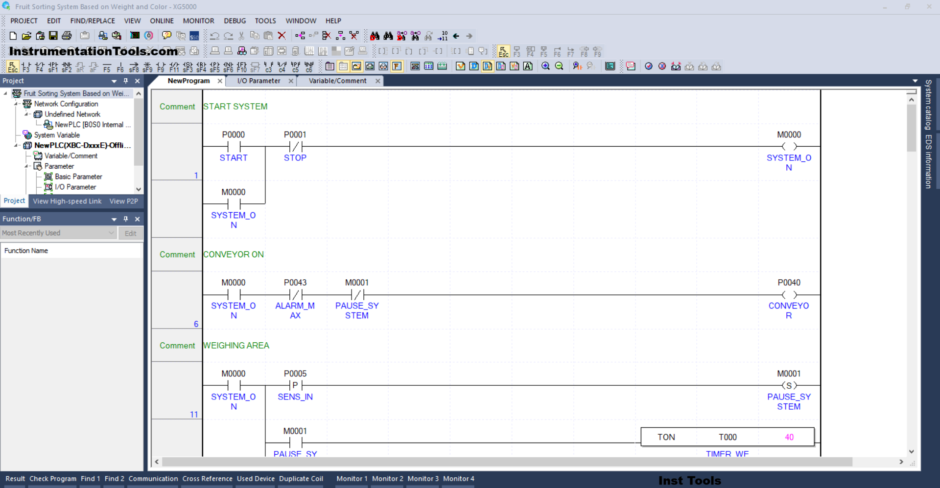
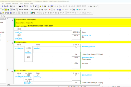
RUNG 1 (START SYSTEM)
In this Rung, when the PB_START (P0000) button is Pressed, the memory bit SYSTEM_ON (M0000) will be in the HIGH state. Because it uses Latching, the memory bit SYSTEM_ON (M0000) will remain in the HIGH state even though the PB_START (P0000) button has been Released.
The memory bit SYSTEM_ON (M0000) will return to the LOW state when the PB_STOP (P0001) button is Pressed.
RUNG 6 (CONVEYOR ON)
In this Rung, the CONVEYOR (P0040) output will be ON if the NO contact of the memory bit SYSTEM_ON (M0000) is in the HIGH state.
The CONVEYOR (P0040) output will be OFF if the NC contact of ALARM_MAX (P0043) or PAUSE_SYSTEM (M0001) is in the HIGH state.
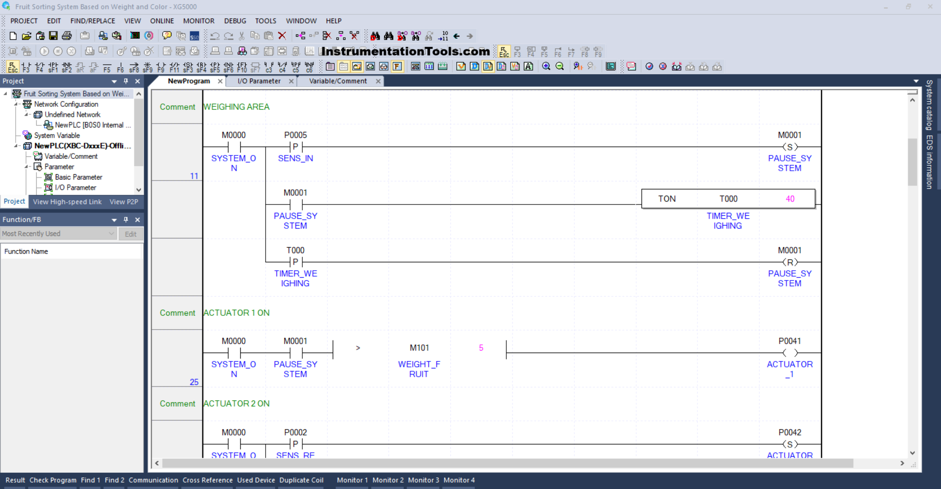
RUNG 11 (WEIGHING AREA)
In this Rung, if the NO contact of the memory bit SYSTEM_ON (M0000) and the SENS_IN (P0005) sensor are in the HIGH state, then the memory bit PAUSE_SYSTEM (M0001) will be in the HIGH state. Because it uses the SET Coil instruction, the memory bit PAUSE_SYSTEM (M0001) will remain in the HIGH state even though the SENS_IN (P0005) sensor is in the LOW state.
The TIMER_WEIGHING (T000) timer will start counting up to 4 seconds when the NO contact of the memory bit PAUSE_SYSTEM (M0001) is in the HIGH state.
When the TIMER_WEIGHING (T000) timer has finished counting, the memory bit PAUSE_SYSTEM (M0001) will be in a LOW state because the RESET Coil instruction from the memory bit PAUSE_SYSTEM (M0001) is triggered from the NO contact of the TIMER_WEIGHING (T000) timer.
RUNG 25 (ACTUATOR 1 ON)
When the NO contacts of the memory bits SYSTEM_ON (M0000) and PAUSE_SYSTEM (M0001) are in the HIGH state and the value in the memory word WEIGHT_FRUIT (M101) is Greater Than “5”, then the output ACTUATOR_1 (P0041) will be ON.

RUNG 31 (ACTUATOR 2 ON)
When the NO contact of the memory bit SYSTEM_ON (M0000) and the SENS_RED (P0002) sensor are in the HIGH state, the ACTUATOR_2 (P0042) output will be ON.
And when the NO contact of the limit switch LS_ACT2 (P0007) is in the HIGH state, the output of ACTUATOR_2 (P0042) will be OFF.
RUNG 41 (ACTUATOR 3 ON)
When the NO contact of the memory bit SYSTEM_ON (M0000) and the SENS_YELLOW (P0003) sensor are in the HIGH state, the ACTUATOR_3 (P0044) output will be ON.
And when the NO contact of the limit switch LS_ACT3 (P0008) is in the HIGH state, the output of ACTUATOR_3 (P0044) will be OFF.
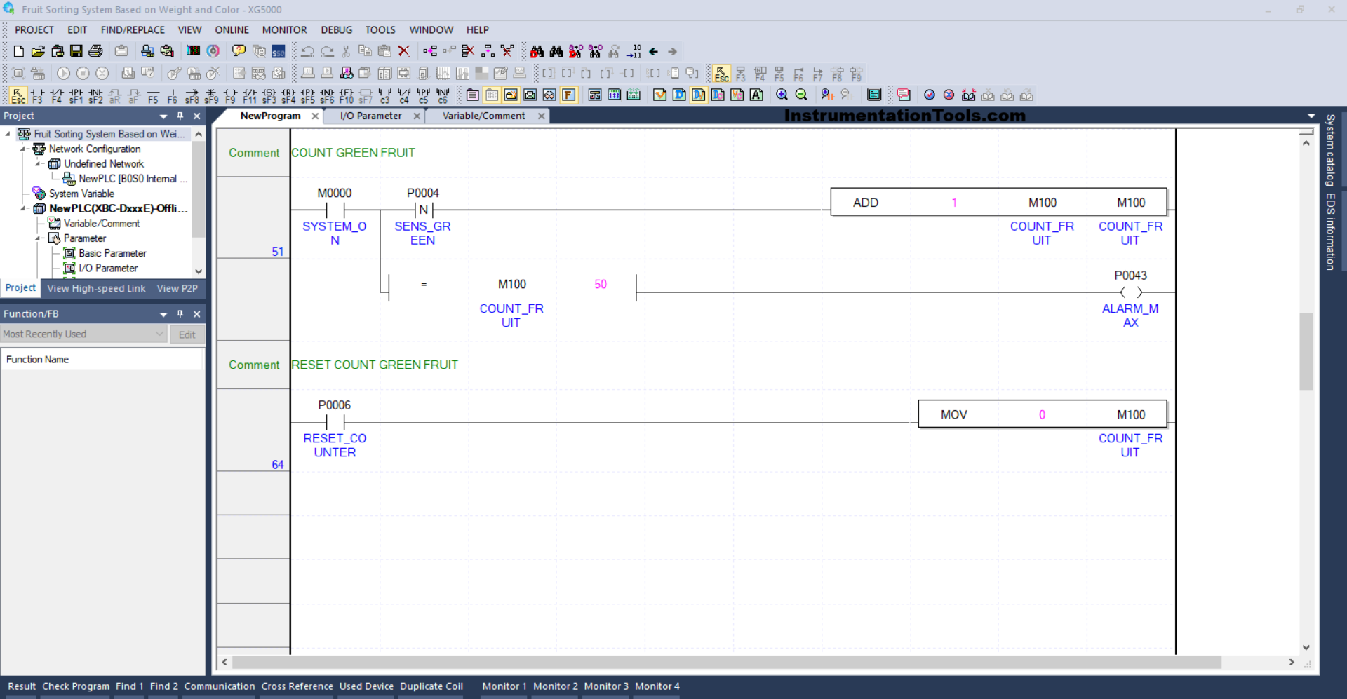
RUNG 51 (COUNT GREEN FRUIT)
When the NO contact of the memory bit SYSTEM_ON (M0000) and the SENS_GREEN (P0004) sensor are in the HIGH state, the value in the memory word COUNT_FRUIT (M100) will increase (+1). Because of the ADD instruction.
And when the value in the memory word COUNT_FRUIT (M100) is Equal To “50”, then the ALARM_MAX (P0043) output will be OFF.
RUNG 64 (RESET COUNT GREEN FRUIT)
When the RESET_COUNTER (P0006) button is Pressed, the value in the memory word COUNT_FRUIT (M100) will be reset to zero “0”. Because the MOV instruction moves the zero value “0” to the memory word COUNT_FRUIT (M100).
Read Next:
- Paint Mixing System Control PLC Program
- OB20 Time Delay Interrupt Organization Block
- PLC OB10 Time of Day Interrupt Organization Block
- Siemens Tia Optimized and Standard Data Block Access
- Difference between Motion Controller and PLC System