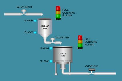
Create a PLC program for the Tank fill and drain logic system using Siemens TIA Portal. The system is designed to regulate the continuous and efficient filling and draining of liquid in a tank. When the liquid level in the tank reaches the minimum limit, the system will automatically initiate the filling process. When the liquid level reaches the maximum limit, the system will carry out the draining process. In addition to operating automatically, the system is also equipped with a manual control feature, allowing users to operate all devices directly if necessary.
Program Objective
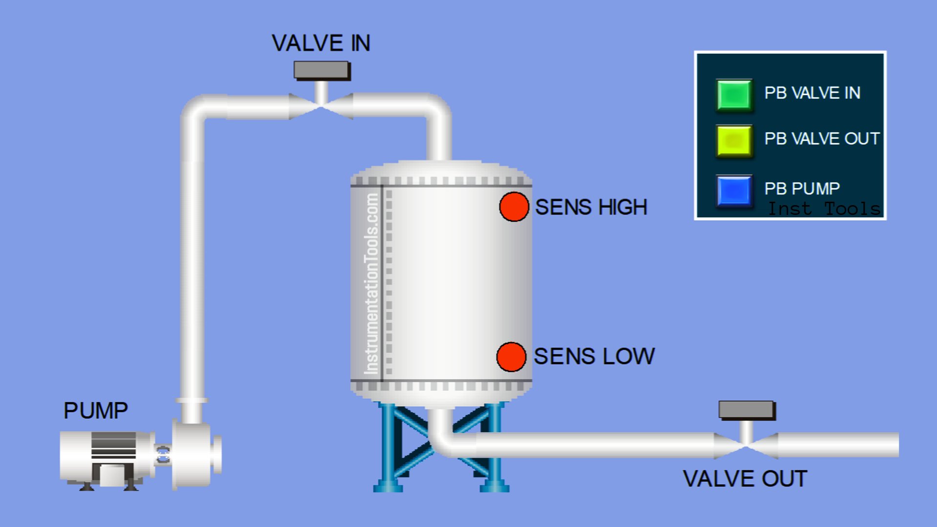
System Step-by-Step Description:
This system is equipped with two operating modes, namely Manual and Auto, which can be selected using a Selector Switch. Below is the detailed explanation:
Auto Mode:
When the water level reaches the minimum limit, the LOW sensor will activate, and the water filling process will begin.
The Input Valve will open, and after 2 seconds, the pump will turn on. The Output Valve remains closed.
When the water level reaches the maximum limit, the HIGH sensor will activate, stopping the filling process and initiating the emptying process.
The Input Valve will close, the pump will turn off, and the Output Valve will open to discharge the liquid from the tank.
This process will repeat continuously as long as the system is in Auto mode.
Manual Mode:
In this mode, the operation of the Input Valve, Output Valve, and Pump is fully controlled manually using the provided buttons. The user has complete control to open, close, or activate these components as needed.
IO Mapping in Siemens TIA-Portal
| S.No. | Comment | Input (I) | Output (Q) | Memory Bits | Timers |
|---|---|---|---|---|---|
| 1 | START | I0.0 | |||
| 2 | STOP | I0.1 | |||
| 3 | MODE | I0.2 | |||
| 4 | PB_PUMP | I0.3 | |||
| 5 | PB_VALVE_IN | I0.4 | |||
| 6 | PB_VALVE_OUT | I0.5 | |||
| 7 | SENS_LOW | I0.6 | |||
| 8 | SENS_HIGH | I0.7 | |||
| 9 | PUMP | Q0.0 | |||
| 10 | VALVE_IN | Q0.1 | |||
| 11 | VALVE_OUT | Q0.2 | |||
| 12 | SYSTEM_ON | M0.0 | |||
| 13 | IR1_PUMP | M0.1 | |||
| 14 | IR1_VALVE_IN | M0.2 | |||
| 15 | IR1_VALVE_OUT | M0.3 | |||
| 16 | IR2_PUMP | M0.4 | |||
| 17 | IR2_VALVE_IN | M0.5 | |||
| 18 | IR2_VALVE_OUT | M0.6 | |||
| 19 | TIMER_PUMP | DB1 |
Create Tank Fill and Drain Logic
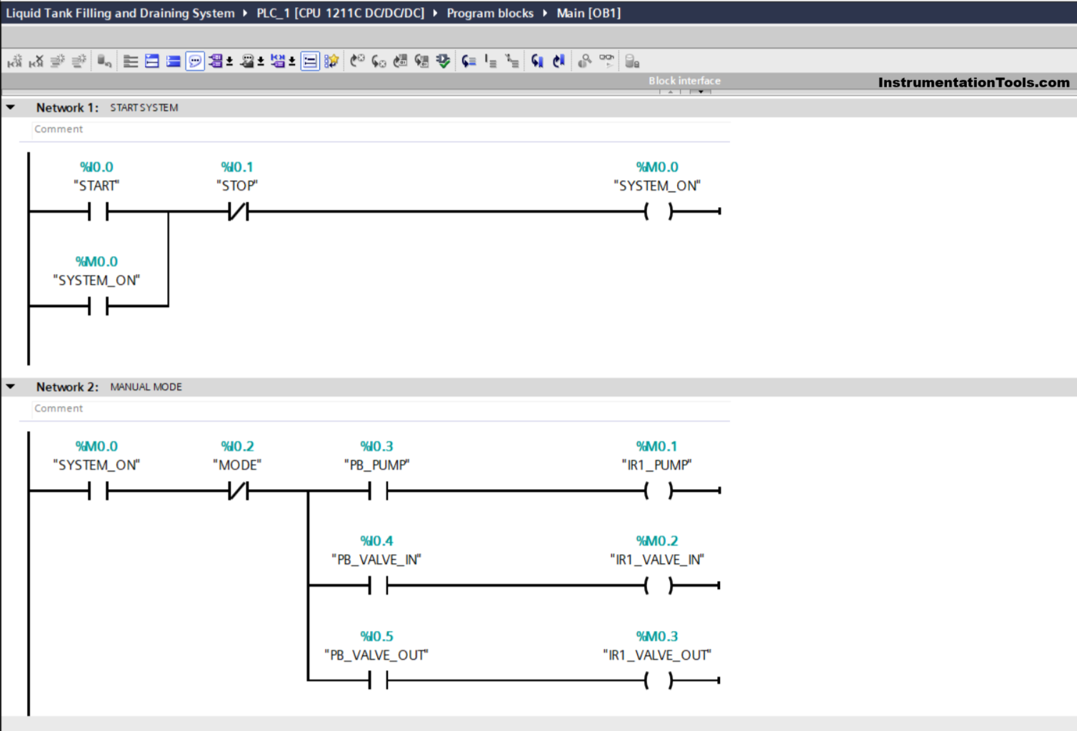
NETWORK 1 (START SYSTEM)
In this Network, the memory bit SYSTEM_ON (M0.0) will be in a HIGH state when the START (I0.0) button is pressed. Even though the START (I0.0) button has been released, the memory bit SYSTEM_ON (M0.0) will remain in a HIGH state. Because it uses Latching.
The memory bit SYSTEM_ON (M0.0) will be in a LOW state if the STOP (I0.1) button is pressed.
NETWORK 2 (MANUAL MODE)
In this Network, the memory bit IR1_PUMP (M0.1) will be in a HIGH state when the NO contact of the memory bit SYSTEM_ON (M0.0) is in a HIGH state and the PB_PUMP (I0.3) button is pressed.
The memory bit IR1_VALVE_IN (M0.2) will be in HIGH state when the NO contact of the memory bit SYSTEM_ON (M0.0) is in HIGH state and the PB_VALVE_IN (I0.4) button is pressed.
And, the memory bit IR1_VALVE_OUT (M0.3) will be in HIGH state when the NO contact of the memory bit SYSTEM_ON (M0.0) is in HIGH state and the PB_VALVE_OUT (I0.5) button is pressed.
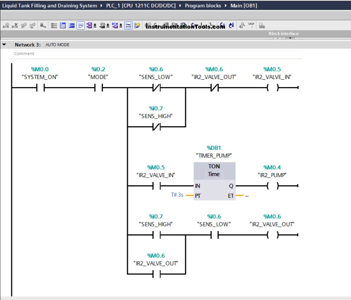
NETWORK 3 (AUTO MODE)
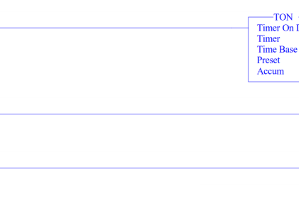
In this Network, the memory bit IR2_VALVE_IN (M0.5) will be in HIGH state when the NO contact of the memory bit SYSTEM_ON (M0.0) and the MODE (I0.2) selector switch are in HIGH state and the NC contact of the SENS_LOW (I0.6) and SENS_HIGH (I0.7) sensors are in LOW state. The TIMER_PUMP (DB1) timer starts counting up to 3 seconds.
When the timer has finished counting, the memory bit IR2_PUMP (M0.6) will be in the HIGH state.
The memory bit IR2_VALVE_OUT (M0.6) will be in HIGH state when the SENS_LOW (I0.6) and SENS_HIGH (I0.7) sensors are in HIGH state.
Next, the memory bit IR2_VALVE_IN (M0.5) will return to the LOW state due to the Interlock from memory bit IR2_VALVE_OUT (M0.6).
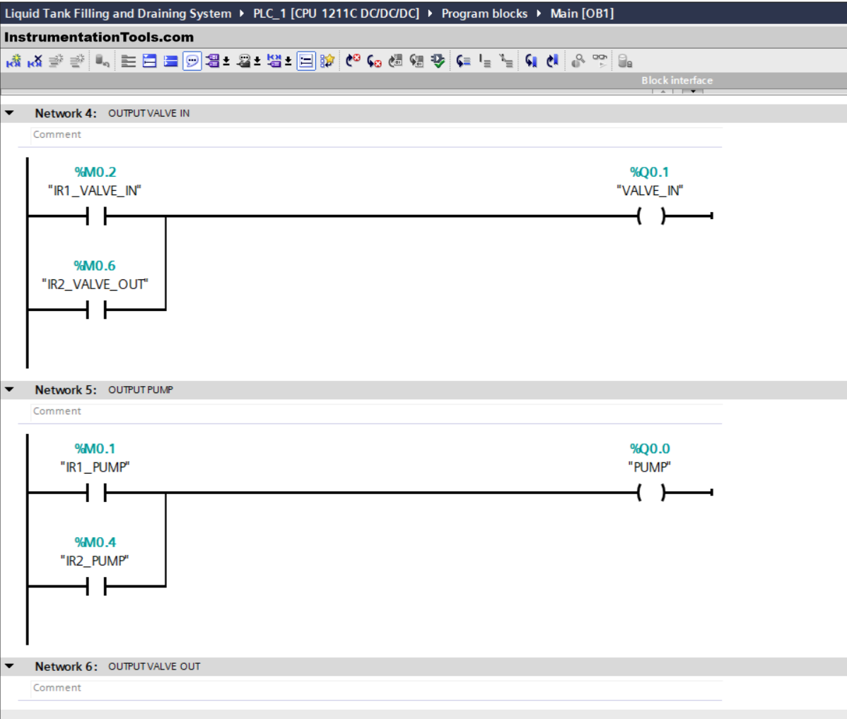
NETWORK 4 (OUTPUT VALVE IN)
In this Network, the output VALVE_IN (Q0.1) will be ON when the NO contact of the memory bits IR1_VALVE_IN (M0.2) or IR2_VALVE_IN (M0.2) is in the HIGH state.
NETWORK 5 (OUTPUT PUMP)
In this Network, the output PUMP (Q0.0) will be ON when the NO contact of the memory bits IR1_PUMP (M0.1) or IR2_PUMP (M0.4) is in the HIGH state.
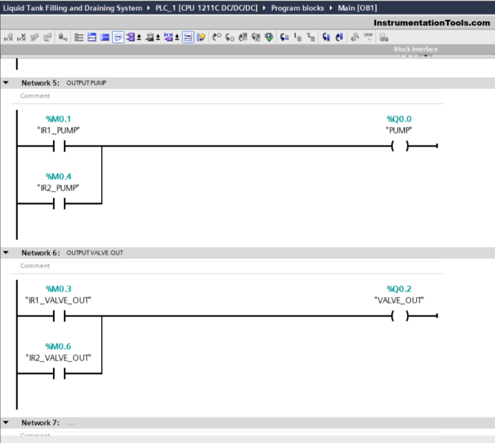
NETWORK 6 (OUTPUT VALVE OUT)
In this Network, the output VALVE_OUT (Q0.2) will be ON when the NO contact of the memory bits IR1_VALVE_OUT (M0.3) or IR2_VALVE_OUT (M0.6) is in the HIGH state.
Read Next:
- Create a Faceplate in FactoryTalk View Studio Tutorial
- Siemens PLC-to-PLC Communication Project Tutorial
- PUT Command in Siemens PLC – TIA Portal Basics
- Siemens Communication between PLCs using I-Device
- Communicating Between Siemens PLC and Other PLCs