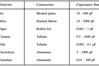
RF level sensors are the Capacitance level detectors which are sometimes called as admittance level sensors. These sensors make use of radio frequency balanced impedance bridge circuit to find out whether the probe is in touch with the process material whose level is going to be detected. “Calibration is done when material is not in contact with the probe. The bridge is balanced by turning the adjustment pot to find the bridge balance threshold. When material comes in contact with the probe, the bridge becomes unbalanced and the comparing circuit realizes the change.” RF level sensors usually work in the low radio frequency megahertz range and measure admittance i.e. conductance in an alternating current circuit which changes with level. Their sensitivity is measured in pico-farads i.e. pF.
A horizontally mounted RF level switch is shown in the figure below.
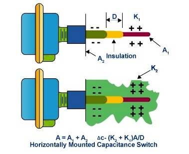
It consists of a conductive probe which serves as one of the capacitor plate, and the vessel wall which forms the other plate of capacitor since it is also prepared from a conductive material. The isolation between these two plates of capacitor is provided via an insulating process material having low dielectric constant. Now, for measurement purpose, an RF signal is applied between the two capacitor plates which causes a little flow of current from the conductive probe to the vessel wall via process material. The probe works as an antenna to sense the frequency. “When the level in the tank drops and the probe is exposed to the even less conductive vapors, the dielectric constant drops. This causes a drop in the capacitance reading and a minute drop in current flow. This change is detected by the level switch’s internal circuitry and translated into a change in the relay state of the level switch.”
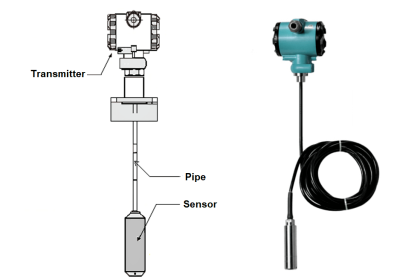
The most widely used probe design includes a stainless steel rod having a diameter of 1 or 1/2 inches. This design is considered appropriate for nearly all non-conductive and non-corrosive substances. The most popular low-dielectric insulating materials used with the probe consist of Nylon or Ryton. The electronic circuitry of the probe has a solid state construction and it mainly carries out following tasks:
- It filters and corrects the input power supply
- It produces the required radio frequency signal
- It detects the variations in flow of current
- It manages and controls interface devices like relays, analog signal generators and display meters.
The circuitry is also granted with provisions to regulate sensitivity and time delays with the help of potentiometer adjustments.
In general, an RF Admittance level transmitter works in an identical fashion as a Capacitance transmitter. However, there are two major modifications in the design which include the oscillator buffer and the chopper drive circuits. These two circuits enable separate determination of resistance and capacitance. This is particularly useful in coating applications for level detection. Since, according to the physical laws, the resistance and capacitance of any coating have same value, the error produced due to the coating can be avoided by measuring and deducting it from the overall output. The resulting output is thus very accurate despite of the presence of coating on the probe. However, “RF admittance is intrusive. Insulating granular measurements require special considerations, such as the moisture range and location of the sensing element to minimize errors caused by probe movement.” In case of insulators having varying dielectric constants, the accurate level measurement can be accomplished only if the material under measurement is homogeneous. However, various advanced RF transmitter designs have been made available which offer high class stability, accuracy and distant communication. For best performance and selection of RF level sensors, one must have fairly accurate idea of the electrical nature of the process material.
Advantages
- They work suitably for level detection in case of both liquids and massive solids.
- They can withstand high temperatures, high pressures, high vibrations and several other coarse operating conditions owing to their strong and robust design.
- Since they consist of no moving parts, they are free from wear, plug or jam troubles.
- They are easy to install and calibrate.
- The length of probe in case of RF level sensors can be easily customized depending upon the application.
- They are the most flexible means to provide continuous level measurement.
- They operate over a broad range of pressure which varies from vacuum to 10,000 psi and temperature ranging from cryogenics to around 850oC.
Typical Applications
Major application areas of RF level sensors include:
- They are widely employed for level detection in case of liquids such as water or wastewater, fuels, petroleum products, acids, caustics, corn Syrup etc.
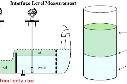
- They can also be applied for level measurement in case of interfaces between liquids such as oil and water, crude and brine, foam and liquid etc.
- They can be used with dry and bulk solids too, for instance, fly ash, cement and sand, plastics, flour and grain, powders, carbon black, wood chips etc.