This article will discuss the complete PLC project for the Traffic Light System that can be run in Auto or Manual mode using the XG-5000 software. When the system is running in Auto mode, the Green, Yellow, and Red lights will turn ON alternately at different time intervals as designed for our application. When the system is running in Manual mode, each light can only be turned ON or OFF using the respective buttons.
Program Objective
The Traffic Light Sequence as follows:
a. Auto Mode:
In the auto mode, the Selector Switch position needs to be changed to “Auto” mode.
- Initial Cycle: When the program is started in automatic mode, the green lamp will be ON first.
- Color Change Sequence: After the Green lamp is ON for 5 seconds, the Yellow lamp will turn ON for 3 seconds. Next, the Red lamp will turn ON for 4 seconds.
- Cycle Repetition: After the Red lamp turns OFF, the cycle will repeat from the beginning, with the Green lamp turning ON again for 5 seconds, and so on.
- Repeating Process: This color changing process will continue to repeat automatically as long as the program is Run in this mode and will stop if the “Stop” button is Pressed.
b. Manual Mode:
In this mode, the Selector Switch needs to be changed to the “Manual” mode, and each lamp can be turned ON or OFF individually using a button.
There are three buttons, each controlling one lamp (Green, Yellow, and Red).
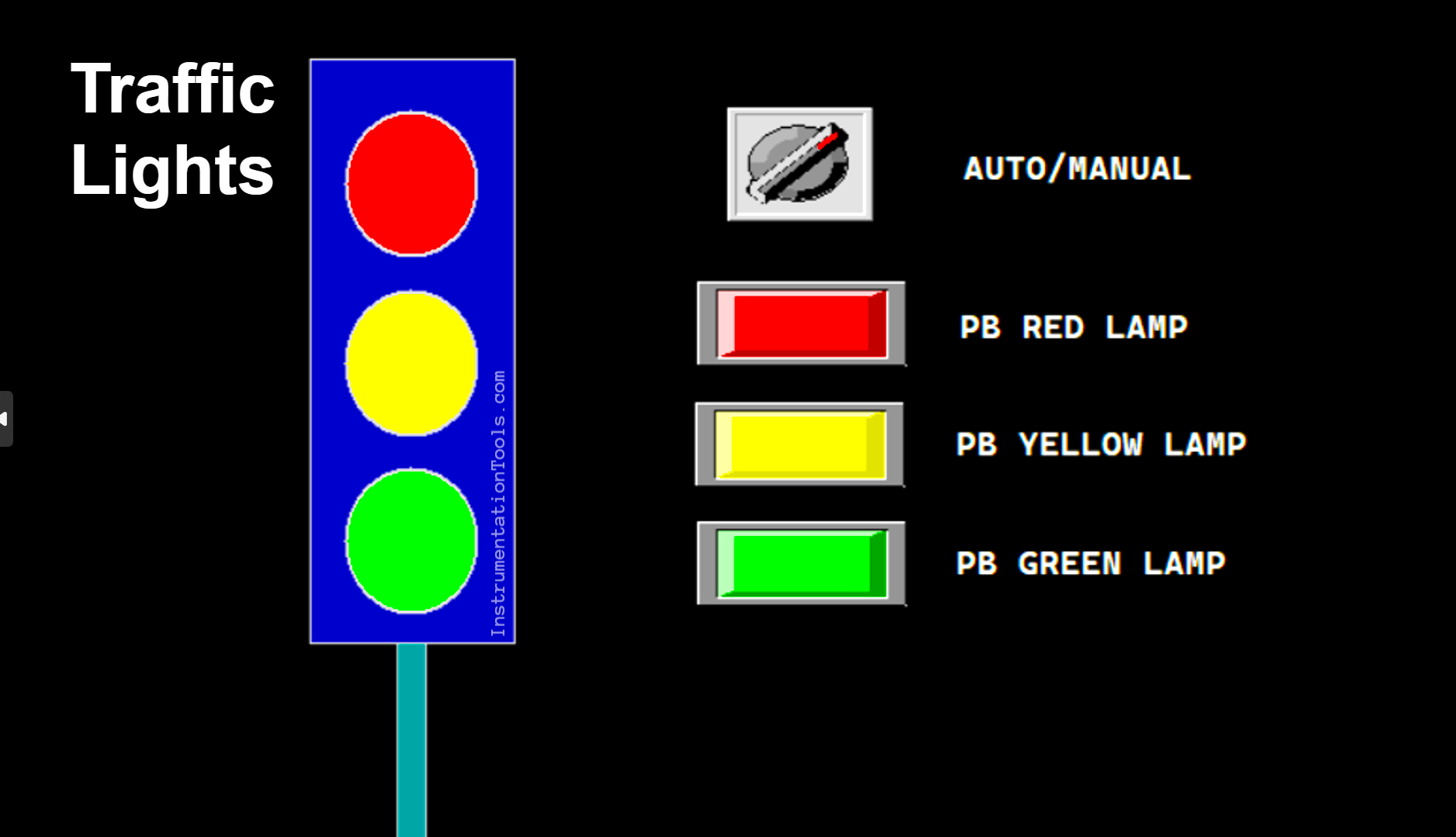
Traffic Light Auto and Manual Automation
Program I/O Details
| S.No. | Comment | Input (I) | Output(Q) | Memory Bit | Timer |
| 1 | START | P0000 | |||
| 2 | STOP | P0001 | |||
| 3 | SELECTOR_SWITCH | P0002 | |||
| 4 | PB_GREEN | P0003 | |||
| 5 | PB_YELLOW | P0004 | |||
| 6 | PB_RED | P0005 | |||
| 7 | LAMP_GREEN | P0040 | |||
| 8 | LAMP_YELLOW | P0041 | |||
| 9 | LAMP_RED | P0042 | |||
| 10 | TIMER1 | T000 | |||
| 11 | TIMER2 | T001 | |||
| 12 | TIMER3 | T002 | |||
| 13 | SYSTEM_ON | M0000 | |||
| 14 | IR_GREEN | M0001 | |||
| 15 | IR_YELLOW | M0002 | |||
| 16 | IR_RED | M0003 |
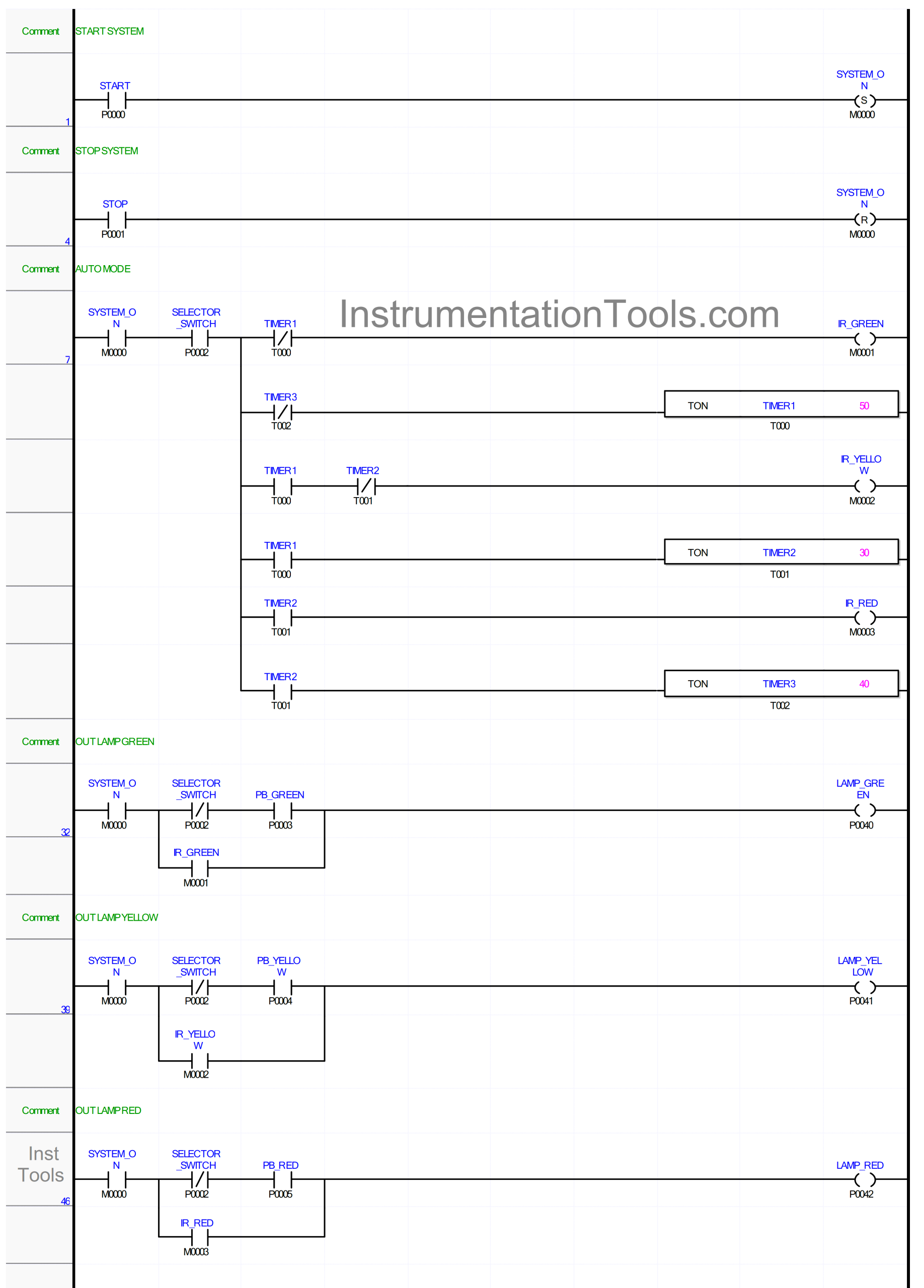
Complete PLC Project
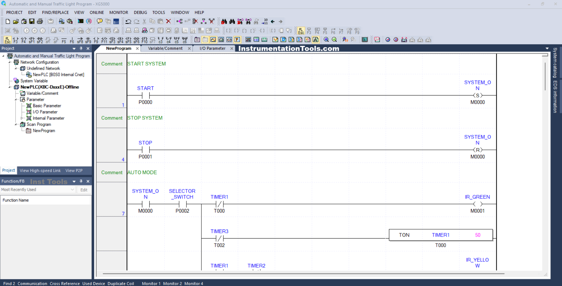
RUNG 1 (START SYSTEM)
In this Rung, the memory bit SYSTEM_ON (M0000) will be in the HIGH state when the START button (P0000) is Pressed. Because it uses the SET Coil Instruction, the memory bit SYSTEM_ON (M0000) will remain in the HIGH state even though the START (P0000) button has been Released.
RUNG 4 (STOP SYSTEM)
In this Rung, the memory bit SYSTEM_ON (M0000) will be in the LOW state if the STOP (P0001) button is Pressed. Because it uses the RESET Coil Instruction, the memory bit SYSTEM_ON (M0000) will remain in the HIGH state even though the STOP (P0001) button has been Released.
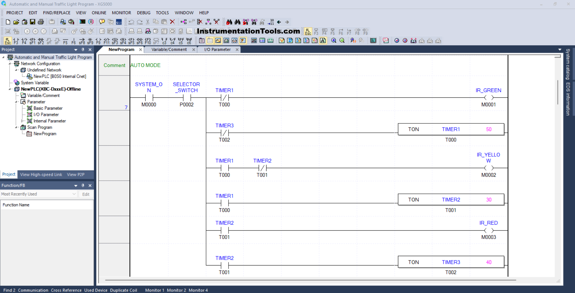
RUNG 7 (AUTO MODE)
In this Rung, when the NO contact of memory bit SYSTEM_ON (M0000) and the NO contact of Selector Switch SELECTOR_SWITCH (P0002) are in the HIGH state, then the memory bit IR_GREEN (M0001) will be in the HIGH state and the timer TIMER1 (T000) will Start counting up to 5 seconds.
When Timer TIMER1 (T000) has finished counting, the memory bit IR_GREEN (M0001) will be in the LOW state, and the memory bit IR_YELLOW (M0002) will be in the HIGH state. Timer TIMER2 (T001) will Start counting up to 3 seconds.
When Timer TIMER2 (T001) has finished counting, the memory bit IR_YELLOW (M0002) will be in the LOW state, and the memory bit IR_RED (M0003) will be in the HIGH state. Timer TIMER3 (T002) will Start counting up to 4 seconds.
Next, when Timer TIMER3 (T002) has finished counting, Timer TIMER1 (T000) will be Reset due to the interlock of Timer TIMER3 (T002).
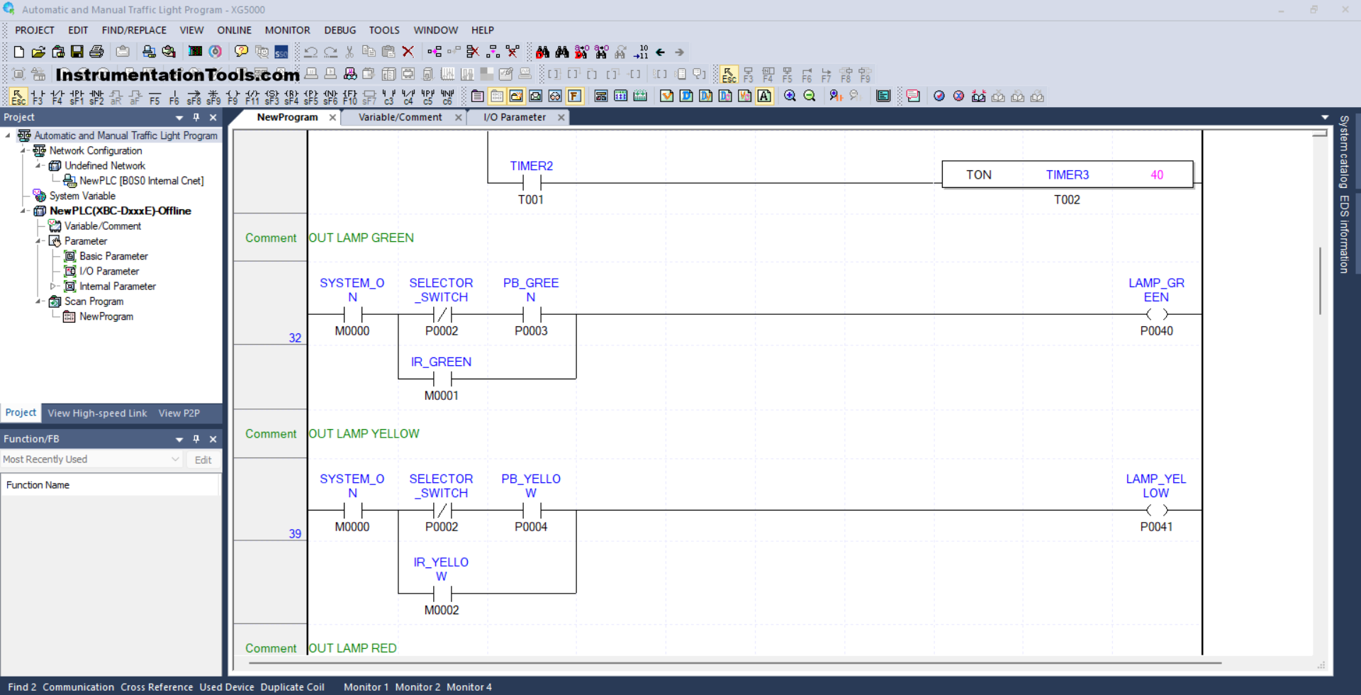
RUNG 32 (OUT LAMP GREEN)
In this Rung, when the NO contact of memory bit SYSTEM_ON (M0000) is in the HIGH state, the NC contact of Selector Switch SELECTOR_SWITCH (P0002) is in the LOW state and the PB_GREEN (P0003) button has been Pressed, then the LAMP_GREEN (P0040) output will be ON. .
Or, if the NO contact of the memory bit IR_GREEN (M0001) is in the HIGH state, then the LAMP_GREEN (P0040) output will be ON.
RUNG 39 (OUT LAMP YELLOW)
In this Rung, when the NO contact of memory bit SYSTEM_ON (M0000) is in the HIGH state, the NC contact of Selector Switch SELECTOR_SWITCH (P0002) is in the LOW state, and the PB_YELLOW (P0004) button has been Pressed, then the output LAMP_YELLOW (P0041) will be ON.
Or, if the NO contact of memory bit IR_YELLOW (M0002) is in the HIGH state, then the LAMP_YELLOW (P0041) output will be ON.
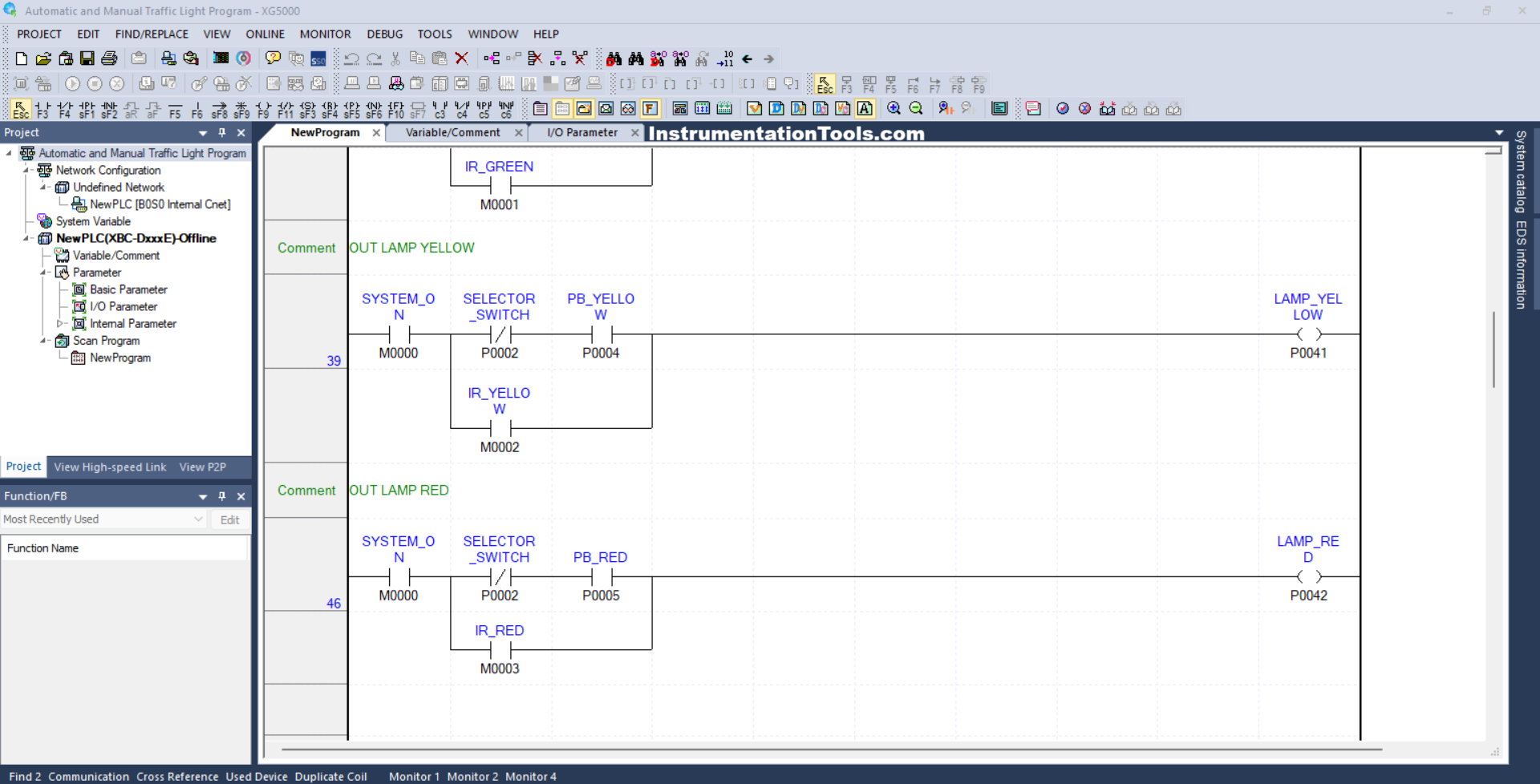
RUNG 46 (OUT LAMP RED)
In this Rung, when the NO contact of memory bit SYSTEM_ON (M0000) in the HIGH state, the NC contact of Selector Switch SELECTOR_SWITCH (P0002) in the LOW state and the PB_ RED (P0005) button has been Pressed, the output LAMP_ RED (P0042) will be to be ON.
Or, if the NO contact of memory bit IR_RED (M0003) is in the HIGH state, then the LAMP_RED (P0042) output will be ON.
Read Next:
- PLC Program for Traffic Light Sequence
- Siemens LOGO PLC Programming Course
- Functional Block Diagram of Studio 5000
- Why is 24 Volts Commonly used in PLC?
- Functional Block Diagram for Traffic Lights