Automatic Motor Forward and reverse control using a timer is one of the finest techniques in industrial automation. In this, we use timers to switch the connection for forward and reverse motor operation without manual involvement. It also improves efficiency, process time, and human errors of operation.
This electrical circuit mainly consists of contactors, relays, and a timer to get the desired output. During this operation, when the timer reaches a preset duration, it controls the movement of the forward and reverse direction of the motor in the circuit. This type of system was mainly used in conveyor belts, machine tools, and automated gates where two directions are necessary. By integrating the timers in the circuit, the process achieves its precise control, giving good performance and reliability in automated operations.
Components Used
The main components used in this electrical circuit are listed below.
- Three Phase Power Supply
- Single Phase Power Supply
- Three Pole Miniature Circuit Breaker
- Three Pole Contactor
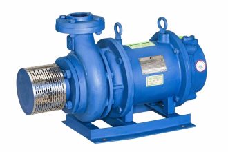
- Motor
- Start and Stop Switch
- Timer
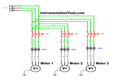
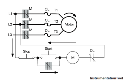
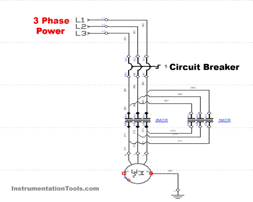
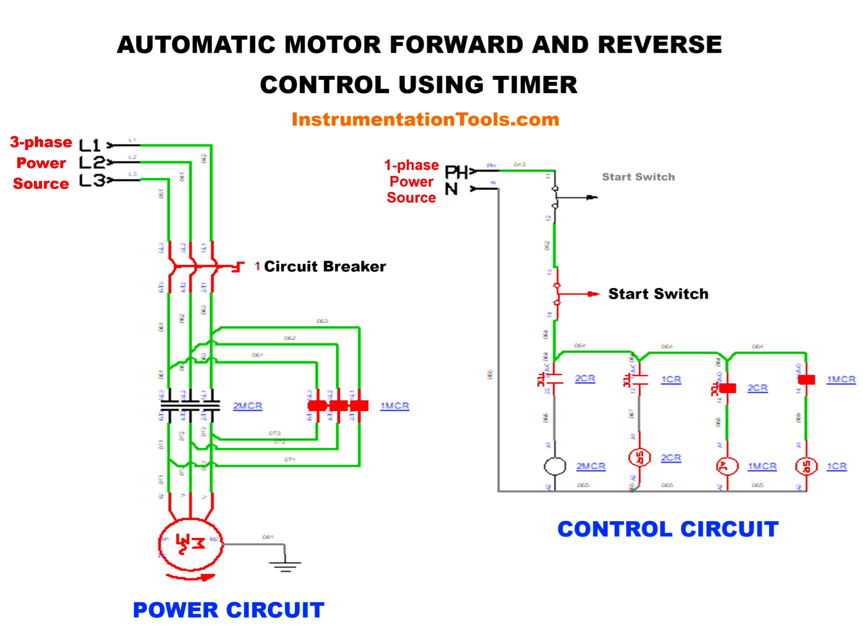
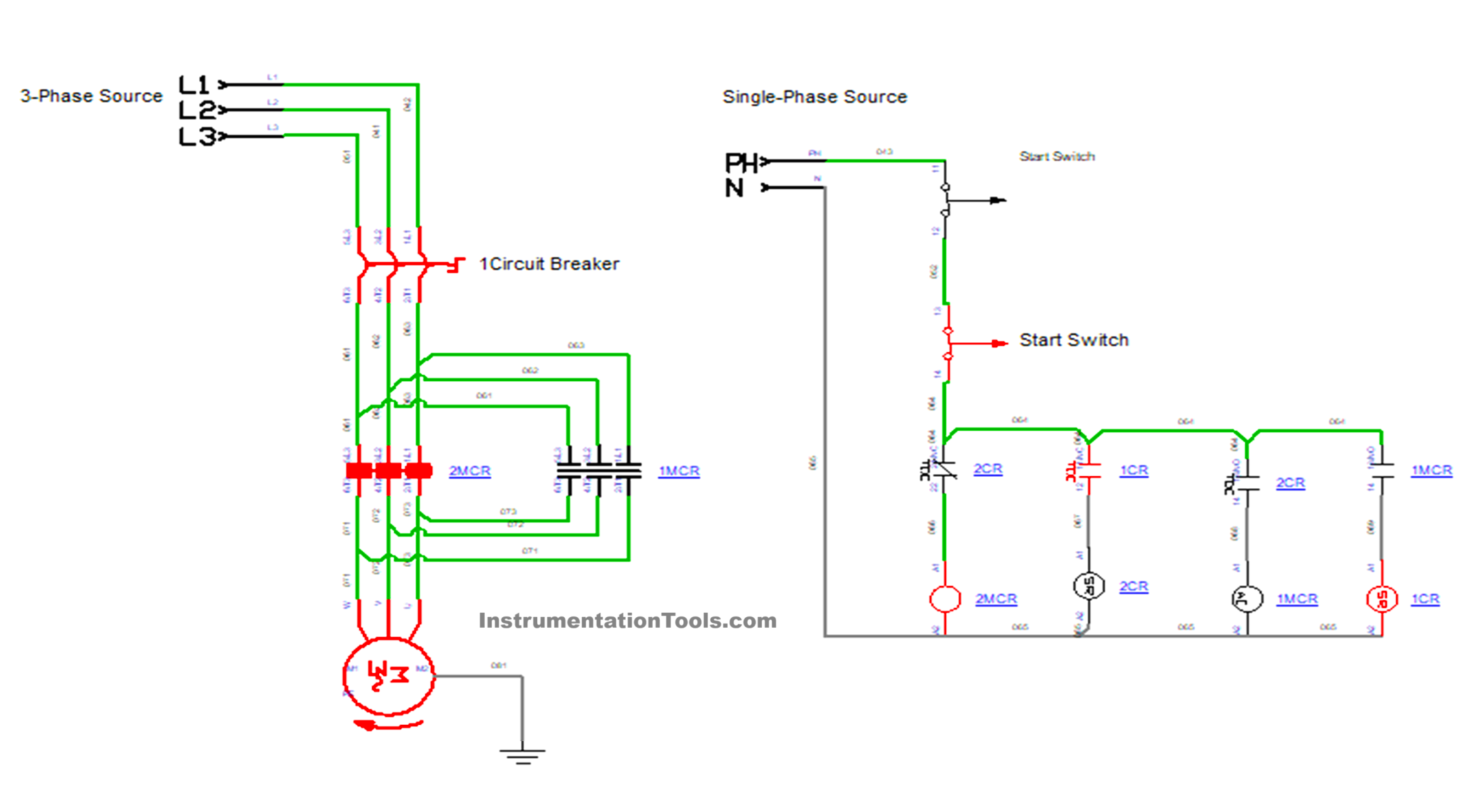
Power Circuit
The power circuit diagram is shown below.
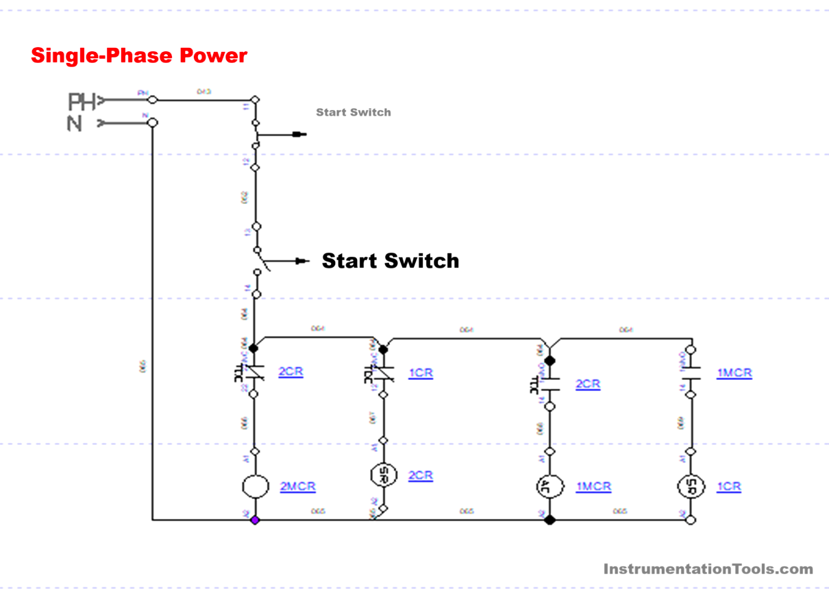
Control Circuit
The control circuit diagram is shown below.
Circuit Operation
- A three-phase supply of 415 V is applied to the system by connecting it to the three pole MCB.
- The output of the MCB was connected with the Forward and reverse contactors for switching and providing the supply
- Single Phase supply of 230 V is applied to the control circuit. The control circuit consists of a start switch, a stop switch, a timer, and contactor coils.
- Single Phase supply is connected with Start and Stop switch. Once the Start button is pressed, it energizes the Motor forward coil (1 MCR), which makes the contactor (1 MCR) operate, and the motor starts to rotate in the Forward direction.
- At the same time, when the forward contactor is energized, the timer ( 1 CR) is also energized.
- Once the preset time is obtained in the timer, the timer coil (1 CR) gets energized, which cuts the supply of the forward contactor coil (1MCR) and energizes the reverse contactor coil (2 MCR) and the second timer (2CR).
- The Reverse Contactor coil (2MCR) will make the reverse contactor (2 MCR) operate and make the motor rotate in the reverse direction, and the second timer (2 CR) will also be in operating condition.
- And once the time was done in the second timer (2CR) it cuts the supply of reverse contactor coil (2 MCR). Then the forward contactor (1 MCR) will operate, and the motor starts to rotate in the forward direction, and this process will continue until the Stop button is pressed.
- Once the Stop button is pressed, the total process will be stopped.
Simulation
Watch this simulation video of the discussed motor circuit.
Conclusion
This method of controlling the motor to rotate in a forward and reverse direction is one of the efficient and reliable methods for controlling the process in the automation sector. In final, this integration of timers in the circuit makes the control for optimizing the performance of the Process, downtime will be less and it develops the safety aspect also. It is also cost effective also, because we are reducing one manpower in the process, which will make the process automation quicker and contribute to efficiency increase and operational effectiveness.
Read Next:
- Automatic Circuit Recloser
- De-energized Electrical Circuits
- How to Locate Faults in Cables?
- Variable Air Volume Controller
- Why is HV Testing important?