Voltage is an electrical parameter which is extremely important when monitoring electrical systems. If you are not able to measure it properly, then you cannot troubleshoot any issue in an electrical system properly. Though voltage sounds simple to listen to, there are many things which can look complex to an engineer when troubleshooting. Each device has it’s operating voltage range, and any issue in measuring it results in further delay in troubleshooting.
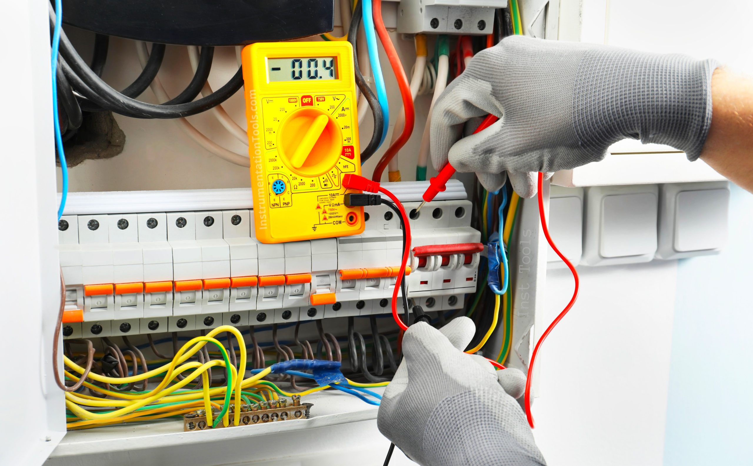
Measuring Voltage
In this post, we will look at some interesting facts that you need to know when measuring voltage.
Do not blindly trust a screw-driver tester
Electricians just touch a screw-driver tester to the point where it is required to check voltage. Yes, the LED inside the tester will glow when voltage is present. But, it is not always trustable. LED glows even in case of leakage current. Sometimes, the LED will be faulty and will not glow even if voltage is present in the circuit. So, just depending on the LED for voltage testing is the wrong thing. It can help you in minor troubleshooting, but cannot be relied on. You will require standard tools like multimeters and voltage testers for coming to a correct conclusion.
Voltage cannot be measured by a single lead
Voltage is the potential difference between two points. It is not like you connect just one lead of a testing device to the point. You will never get an answer to this. Voltage is always measured between two points; not on a single point. Even if both the points are down or faulty, the leads will be connected to both these points. So, if you are sure about the positive point of the voltage, you also need to find it’s correct negative point. It should not be like you have connected positive lead to a different potential and negative lead to a different potential. Voltage is not only the difference between plus and minus; because there can be many plus and minus points in the circuit. So, you cannot connect the plus point of the 1st power supply to the minus point of the 2nd power supply. You will never get an answer.
Choose the correct measurement parameter
You have connected your multimeter to a 230V AC socket, and kept the settings of the meter in DC voltage. What will happen? The meter will blast or the wires will get burnt. Both the voltages are different. In short, the same will happen if you connect your meter to a 6000V DC transformer and keep the meter in AC voltage (maximum till 1000V). In short, you need to know the maximum voltage of the point where you are placing your testing device. The testing device should always be a higher voltage or equal to the voltage you are testing the points at. Also, just for the sake of voltage difference, do not connect AC to DC point or vice-versa, thinking nothing will happen. Electronics are unpredictable and any malfunction can best be avoided by connecting correct potentials.
Do not consider electrostatic voltage lightly
You must have seen how you rub your comb to a surface like wood or plastic, and bring it near a piece of paper. The paper will be attracted to the comb. This is electrostatic voltage. It is present everywhere in our day to day lives. If this voltage is present near a high voltage area, then definitely it’s value will be higher. They just wait for something to be touched to it, which then creates a spark. So, whenever you are dealing with testing voltages, remember where you are present, where you are touching and what is the nearby environment. This will help you in testing your work safely.
Take care when changing the leads of the meter
You have connected your lead to a point of 230V AC and decide to test a device of higher voltage. As discussed earlier, low test potential of the meter can damage itself when touched to a higher one. So, before testing any device, remove the leads from your points and check the current position of the meter probe. Set it correctly and then connect your leads.
Do not worry if the reading shows negative voltage
This concept is pretty simple to understand. If you connect the positive lead of your meter to the negative point of the device to be tested, and vice-versa, voltage will show as negative in the meter. So, it is not like something is wrong. You will get the correct voltage value; the only thing is that a negative sign will also be shown. So, just interchange the leads and the voltage will now be shown with correct potentials. It thus shows that it is just a matter of display and has no relation with the voltage value as it will be correct.
Do not expect exact readings of the voltage every time
Digital and analog instruments measuring voltage always have a slight span of error in them. It cannot give you exact real time voltage values, as it will differ in a minute point. For example, if the voltage is 220.34 V, then it may show you as 220.28 V or 220.40 V. The tolerance range varies depending on the instrument quality, voltage transients present, and quality of the voltage. A small spike in voltage can be manageable by the engineers and they will get a proper idea on the voltage present in the circuit.
A tiny current will flow through the meter probes
When probes are connected to a device or point to test, some minute current will flow through the probes from the load. It is very tiny and almost negligible. And as extra current is drawn, the resistance of the point drops a little. It does not matter for heavy loads, but affects smaller loads. In such loads, the resistance of the load is almost equal to that of the meter. And the resistance will drop hugely if the meter is connected.
Current can pass through the air
Many do not know this but yes, if the voltage difference between two points is very high, then current can pass through the air between them. A very high voltage can break the insulation properties of the air and allow current to flow. So, while working in high voltage areas, take special care when measuring voltages.
In this way, we saw things to know when measuring voltage.
Read Next:
- Electric Stress Control in Cables & Terminations
- Why Circuit Breakers Don’t Protect People?
- Compare Short Circuit and Ground Fault
- Things to Know When Measuring Current
- What is a Gas-Insulated Transmission Line?