This article discusses an example of a PLC program to automatically control the railway crossing system with train detection and gate operation. This system is used to control the process of Opening and Closing railway crossing gates when a train passes. This system uses sensors to detect the arrival and departure of trains. When the system detects a train is coming, the system will automatically Close the crossing gates and Activate a warning Alarm. The system will re-Open the crossing gates after the train has passed the crossing, and the Alarm will be turned Off.
Train Detection and Gate Operation
The PLC program uses 2 buttons and 4 sensors, the START_SYSTEM (I0.0) button is used to turn ON the system, and the STOP_SYSTEM (I0.1) button is used to turn OFF the system.
The SENS_TRAIN_COME (I0.2) sensor is used to detect an oncoming train, the SENS_TRAIN_LEFT (I0.3) sensor is used to detect a train that has passed a railway crossing, SENS_GATE_DOWN (I0.5) is used to limit the Gate position when Closing, and SENS_GATE_UP (I0.4) is used to limit the Gate position when Opening.
When a Train Comes
The SENS_TRAIN_COME (I0.2) sensor will be Active when it detects an oncoming train. The crossing gate will move CLOSED and the Output OUT_GATE_DOWN (Q0.1) will be ON. Alarm OUT_ALARM (Q0.2) becomes ON to provide a warning.
The crossing gate will Stop Closing when the SENS_GATE_DOWN (I0.5) sensor is Active, so the OUT_GATE_DOWN (Q0.1) Output will become OFF.
When a train has passed
The SENS_TRAIN_LEFT (I0.3) sensor will be Active when it detects that a train has passed a train crossing. 4 seconds later the crossing gate will OPEN. Output OUT_GATE_UP (Q0.0) becomes ON and Alarm OUT_ALARM (Q0.2) becomes OFF.
The OUT_GATE_UP (Q0.0) output will be OFF when the SENS_GATE_UP (I0.4) sensor is Active so that the crossing gate Stops Opening.
Program Addressing
| Comment | Input (I) | Output (Q) | Memory Bits | Timer |
| START_SYSTEM | I0.0 | |||
| STOP_SYSTEM | I0.1 | |||
| SENS_TRAIN_COME | I0.2 | |||
| SENS_GATE_DOWN | I0.5 | |||
| SENS_TRAIN_LEFT | I0.3 | |||
| SENS_GATE_UP | I0.4 | |||
| OUT_GATE_DOWN | Q0.1 | |||
| OUT_GATE_UP | Q0.0 | |||
| OUT_ALARM | Q0.2 | |||
| SYSTEM_ON | M0 | |||
| IR_GATE_DOWN | M2 | |||
| IR_GATE_UP | M1 | |||
| IR_ALARM | M3 | |||
| IR_TIMER | M4 | |||
| TIMER_GATE | TM0 |
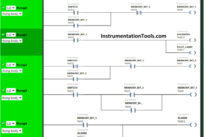
Programming
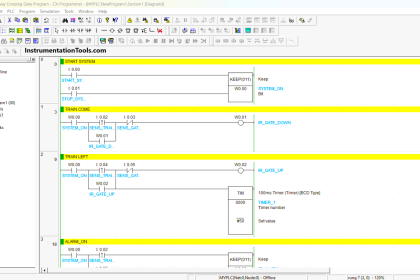
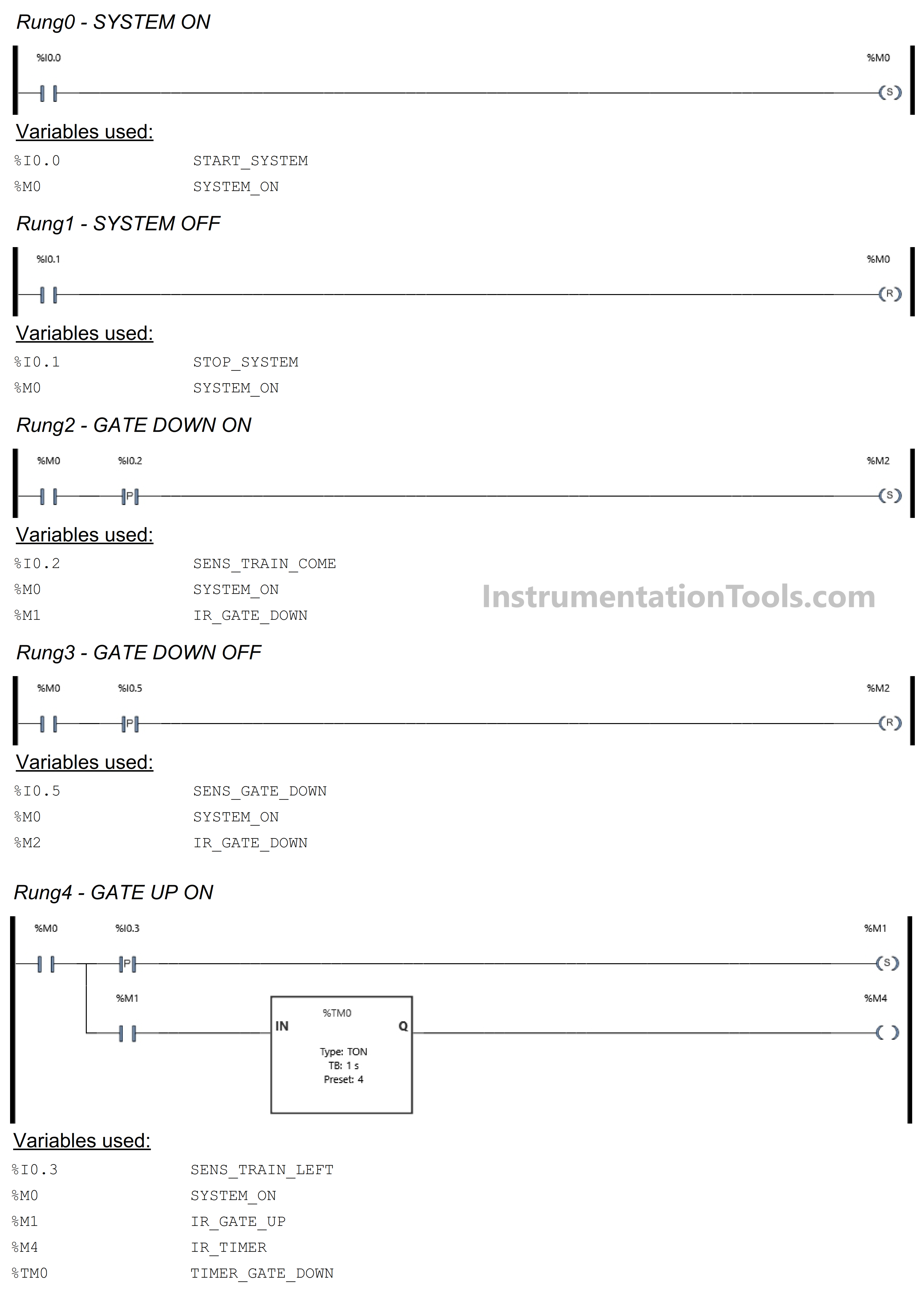
RUNG 0 (SYSTEM ON)
In this Rung, when the START_SYSTEM (I0.0) button is Pressed, the memory bit SYSTEM_ON (M0) will be in the HIGH state. The memory bit SYSTEM_ON (M0) remains in the HIGH state even though the START_SYSTEM (I0.0) button has been Released, because it uses the SET Coil Instruction.
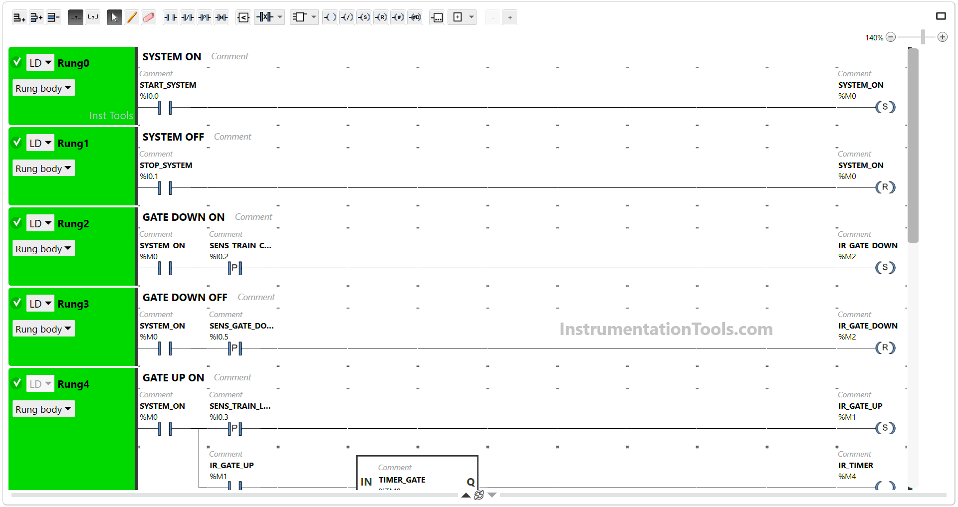
RUNG 1 (SYSTEM OFF)
In this Rung, if the STOP_SYSTEM (I0.1) button is Pressed, the memory bit SYSTEM_ON (M0) will become LOW state. Because it uses the RESET Coil Instruction.
RUNG 2 (GATE DOWN ON)
In this Rung, when the NO contact of memory bit SYSTEM_ON (M0) and the SENS_TRAIN_COME (I0.2) sensor in the HIGH state, then the memory bit IR_GATE_DOWN (M2) will be in the HIGH state.
Because it uses the SET Coil Instruction, the memory bit IR_GATE_DOWN (M2) will remain in the HIGH state even though the SENS_TRAIN_COME (I0.2) sensor in the LOW state.
RUNG 3 (GATE DOWN OFF)
In this Rung, when the NO contact of memory bit SYSTEM_ON (M0) and the SENS_GATE_DOWN (I0.5) sensor in the HIGH state, the memory bit IR_GATE_DOWN (M2) will be in the LOW state. Because it uses the RESET Coil Instruction.
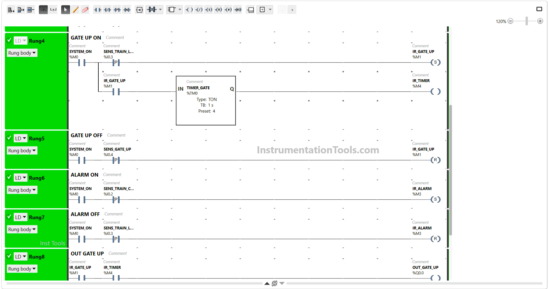
RUNG 4 (GATE UP ON)
In this Rung, when the NO contact of memory bit SYSTEM_ON (M0) and the SENS_TRAIN_LEFT (I0.3) sensor in the HIGH state, then the memory bit IR_GATE_UP (M1) will become in the HIGH state and the TIMER_GATE (TM0) timer Starts counting up to 4 second.
Because it uses the SET Coil Instruction, the memory bit IR_GATE_UP (M1) will remain in the HIGH state even though the SENS_TRAIN_LEFT (I0.3) sensor in the LOW state.
After TIMER_GATE (TM0) has finished counting, the output memory bit IR_TIMER (M4) will be in the HIGH state.
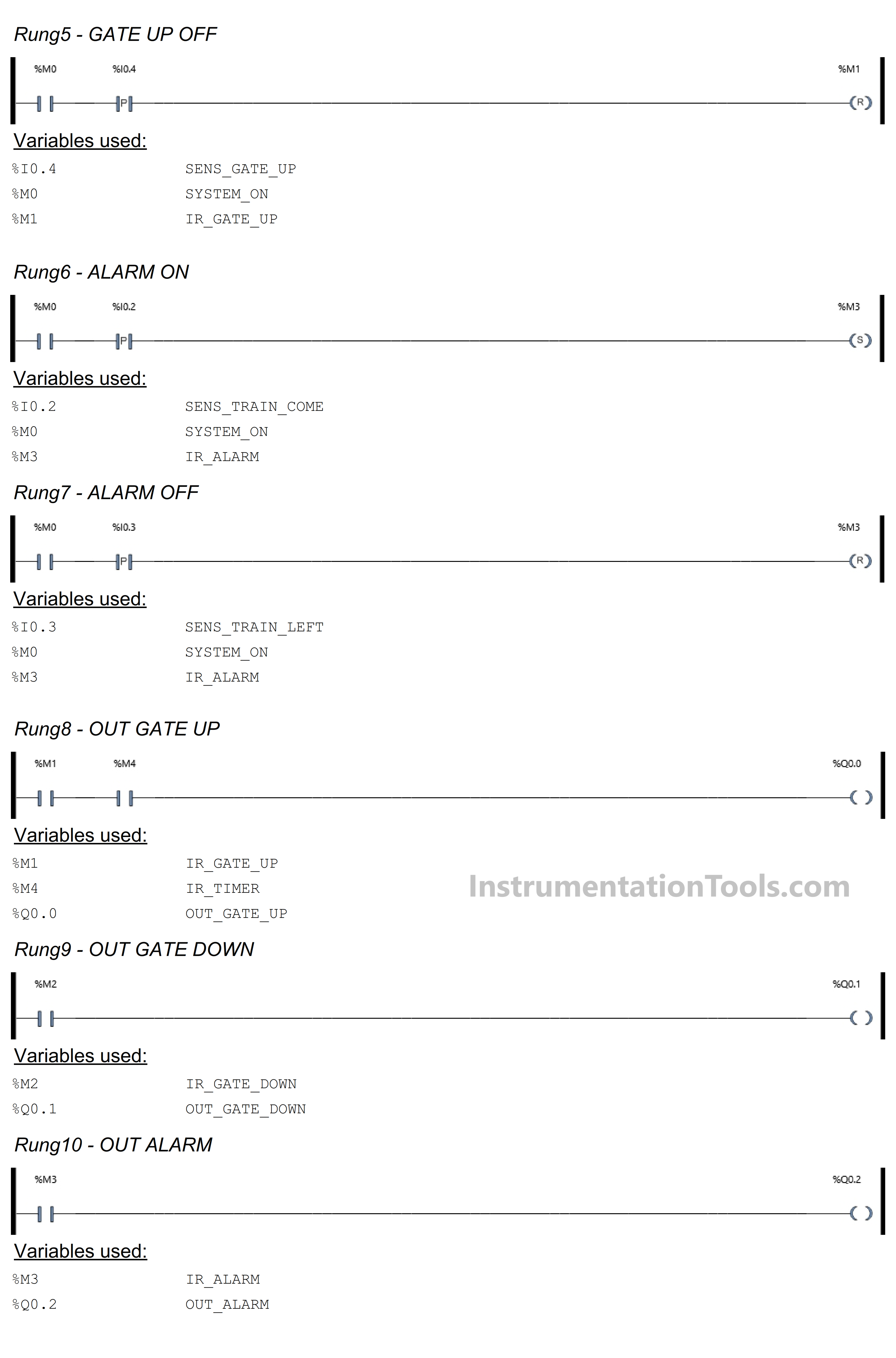
RUNG 5 (GATE UP OFF)
In this Rung, if the NO contact of memory bit SYSTEM_ON (M0) and the SENS_GATE_UP (I0.4) sensor in the HIGH state, then the memory bit IR_GATE_UP (M1) will be in the LOW state. Because it uses the RESET Coil Instruction.
RUNG 6 (ALARM ON)
In this Rung, the memory bit IR_ALARM (M3) will be in the HIGH state when the NO contacts of memory bit SYSTEM_ON (M0) and the SENS_TRAIN_COME (I0.2) sensor are in the HIGH state.
Because it uses a SET Coil, the memory bit IR_ALARM (M3) remains in the HIGH state even though the SENS_TRAIN_COME (I0.2) sensor in the LOW state.
RUNG 7 (ALARM OFF)
When the NO contact of memory bit SYSTEM_ON (M0) and the SENS_TRAIN_LEFT (I0.3) sensor in the HIGH state, the memory bit IR_ALARM (M3) will be in the LOW state. Because it uses the RESET Coil Instruction.
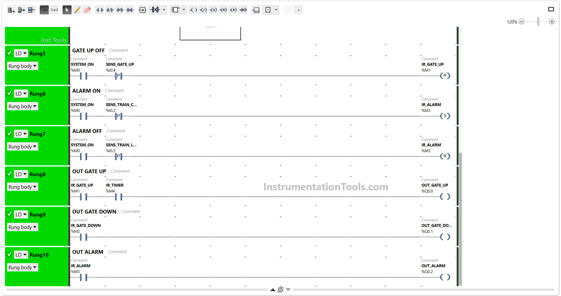
RUNG 8 (OUT GATE UP)
In this Rung, when the NO contacts of memory bit IR_GATE_UP (M1) and IR_TIMER (M4) are in the HIGH state, the Output OUT_GATE_UP (Q0.0) will be ON.
RUNG 9 (OUT GATE DOWN)
In this Rung, when the NO contact of memory bit IR_GATE_DOWN (M2) in the HIGH state, the Output OUT_GATE_DOWN (Q0.1) will be ON.
RUNG 10 (ALARM OUTPUT)
In this Rung, when the NO contact of memory bit IR_ALARM (M3) in the HIGH state, the Output OUT_ALARM (Q0.2) will be ON.
Read Next:
- PLC Product Painting with Weighing System
- Studio 5000 PLC Program for Digital Alarms
- Vacuum Cleaner Programming in Omron PLC
- Washing Machine Automation PLC Program
- Functional Block Diagram Analog Alarm Logic