This article discusses the Sequential Batch Perfume Mixing & Filling system which can be used as a learning medium for students or beginner PLC programmers.
Perfume Mixing and Filling System
This PLC system has 2 buttons, the START_SYSTEM (0.00) button is used to Turn ON the system, and the STOP_SYSTEM (0.01) button is used to Turn OFF the system.
When the START_SYSTEM (0.00) button is pressed, the Output VALVE_INPUT_PERFUME (100.00) will OPEN to carry out the Liquid Filling process. The Output VALVE_INPUT_PERFUME (100.00) will CLOSE when the Mixer tank has been filled to 100kg.
When the Filling process is complete, the MIXER Output (100.01) will be ON to carry out the Mixing process for 15 seconds. When the MIXER Output (100.01) is OFF, the system will be in Standby Mode.
This PLC system has 3 sensors which are used to detect VAT Perfume.
When VAT_SENSOR1 (0.02) is HIGH because it detects VAT Perfume, the Output VALVE_OUT_PERFUME1 (100.02) will OPEN for 5 seconds to drain liquid into VAT Perfume.
When VAT_SENSOR2 (0.03) is HIGH because it detects VAT Perfume, the Output VALVE_OUT_PERFUME2 (100.03) will OPEN for 5 seconds to drain the liquid into VAT Perfume.
When VAT_SENSOR3 (0.04) is HIGH because it detects VAT Perfume, the Output VALVE_OUT_PERFUME3 (100.04) will OPEN for 5 seconds to drain liquid into VAT Perfume.
The system will turn OFF when the liquid in the Mixer tank is empty.
PLC Inputs and Outputs Details
| Comment | Input (I) | Output(Q) | Memory Bits | Memory Word | Timers |
| START_SYSTEM | 0.00 | ||||
| STOP_SYSTEM | 0.01 | ||||
| VAT_SENSOR1 | 0.02 | ||||
| VAT_SENSOR2 | 0.03 | ||||
| VAT_SENSOR3 | 0.04 | ||||
| VALVE_INPUT_PERFUME | 100.00 | ||||
| MIXER | 100.01 | ||||
| VALVE_OUT_PERFUME1 | 100.02 | ||||
| VALVE_OUT_PERFUME2 | 100.03 | ||||
| VALVE_OUT_PERFUME3 | 100.04 | ||||
| TIMER_MIXER | T0000 | ||||
| TIMER_PERFUME1 | T0001 | ||||
| TIMER_PERFUME2 | T0002 | ||||
| TIMER_PERFUME3 | T0003 | ||||
| SYSTEM_ON | W0.00 | ||||
| STANDBY_MODE | W0.01 | ||||
| SYSTEM_OFF | W0.02 | ||||
| PERFUME_WEIGHT | D0 |
CX-Programmer Example
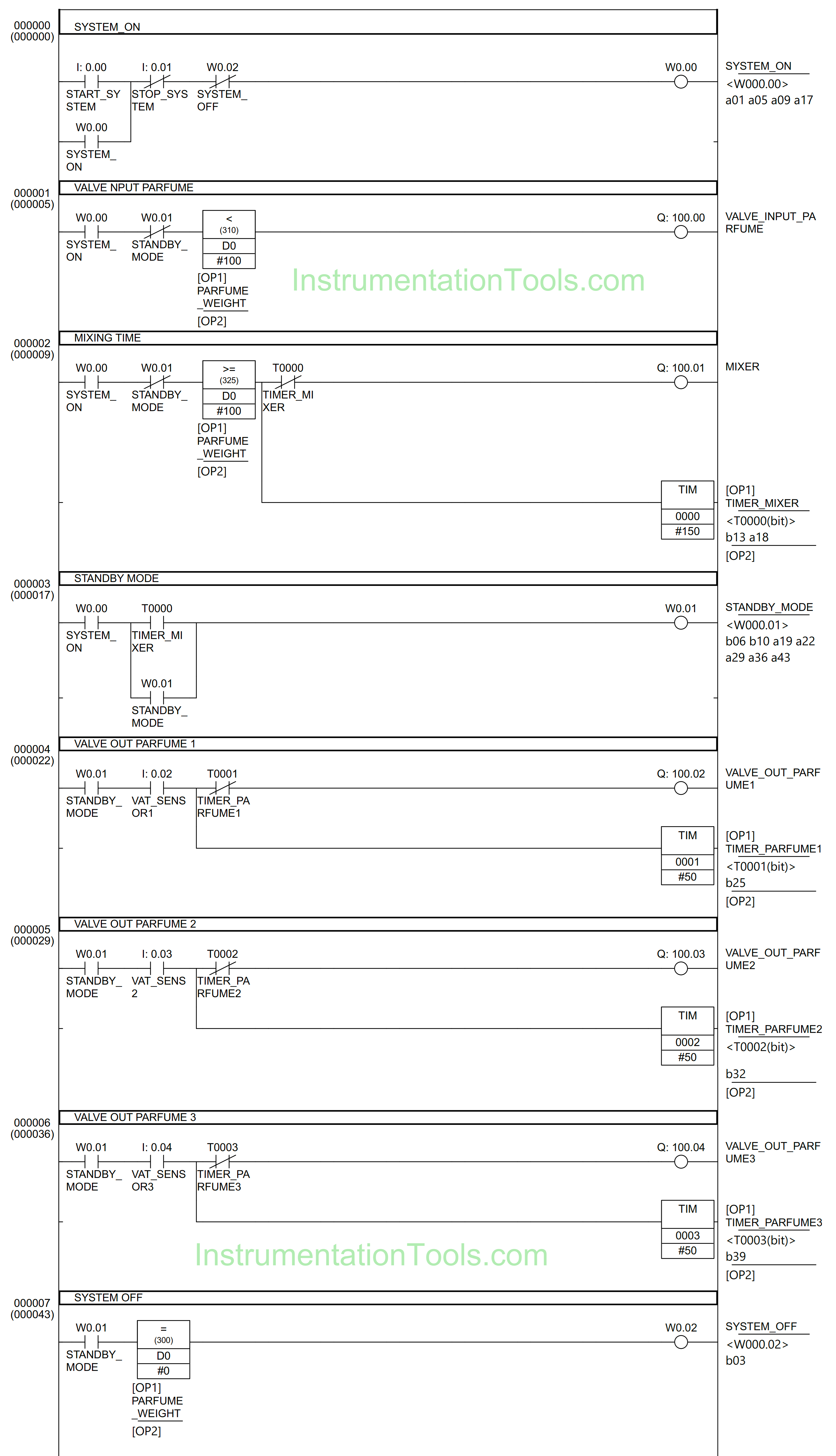
RUNG 0 (SYSTEM_ON)
In this Rung, when the START_SYSTEM (0.00) button is pressed, the memory bit SYSTEM_ON (W0.00) changes to the HIGH state. Because it uses Latching, the memory bit SYSTEM_ON (W0.00) remains in the HIGH state even though the START_SYSTEM (0.00) button has been Released.
The memory bit SYSTEM_ON (W0.00) will change to a LOW state if the STOP_SYSTEM (0.01) button is pressed or when the NC contact of the memory bit SYSTEM_OFF (W0.02) in the HIGH state.
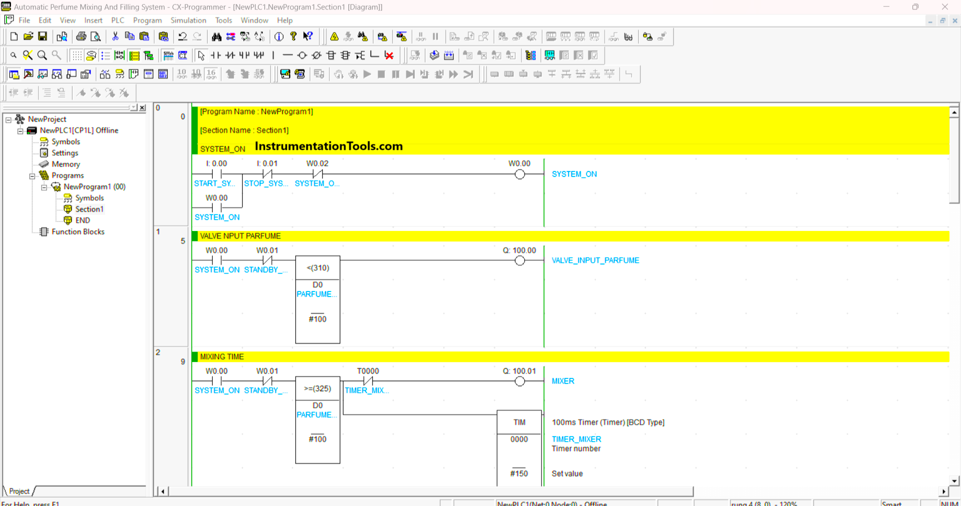
RUNG 1 (PERFUME INPUT VALVE)
The VALVE_INPUT_PERFUME (100.00) Output will be OPEN when the NO contact of memory bit SYSTEM_ON (W0.00) in HIGH state and the value in memory word PERFUME_WEIGHT (D0) is less than “100”.
RUNG 2 (MIXING TIME)
In this Rung, when the NO contact of memory bit SYSTEM_ON (W0.00) in HIGH state and the value in memory word PERFUME_WEIGHT (D0) is greater than or equal to “100”, then the MIXER (100.01) Output will be ON. The timer TIMER_MIXER (T0000) will count up to 15 seconds.
The MIXER (100.01) Output will be OFF when the NC contact of memory bit SYSTEM_OFF (W0.02) and timer TIMER_MIXER (T0000) in the HIGH state.
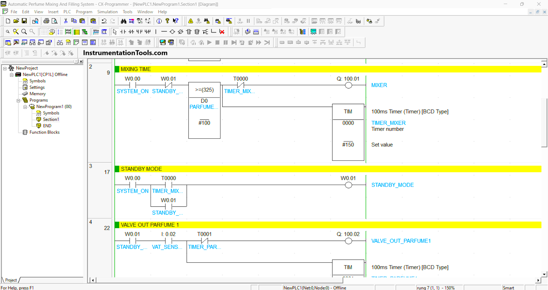
RUNG 3 (STANDBY MODE)
When the NO contact of the memory bit SYSTEM_ON (W0.00) and the timer TIMER_MIXER (T0000) in the HIGH state, the memory bit STANDBY_MODE (W0.01) changes to the HIGH state.
RUNG 4 (VALVE OUT PERFUME 1)
When the NO contact of memory bit STANDBY_MODE (W0.01) and the sensor VAT_SENSOR1 (0.02) in the HIGH state, the VALVE_OUT_PERFUME1 (100.02) Output will be OPEN and the timer TIMER_PERFUME1 (T0001) will Start counting up to 5 seconds.
The VALVE_OUT_PERFUME1 (100.02) Output will be CLOSE when the NO contact of sensor VAT_SENSOR1 (0.02) in the LOW state or the NC contact of timer TIMER_PERFUME1 (T0001) in the HIGH state.
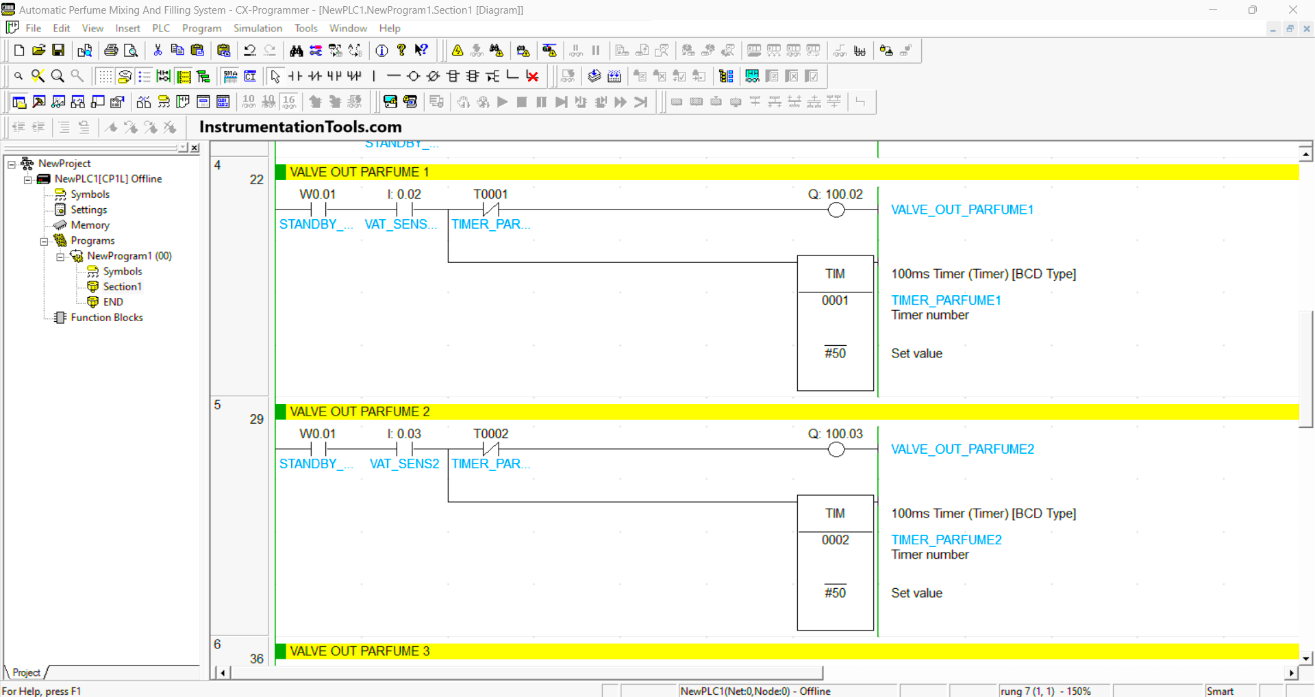
RUNG 5 (VALVE OUT PERFUME 2)
When the NO contact of memory bit STANDBY_MODE (W0.01) and the sensor VAT_SENSOR2 (0.03) in the HIGH state, the VALVE_OUT_PERFUME2 (100.03) Output will be OPEN and the timer TIMER_PERFUME2 (T0002) will Start counting up to 5 seconds.
The VALVE_OUT_PERFUME2 (100.03) Output will be CLOSE when the NO contact of sensor VAT_SENSOR2 (0.03) in the LOW state or the NC contact of timer TIMER_PERFUME2 (T0002) in the HIGH state.
RUNG 6 (VALVE OUT PERFUME 3)
When the NO contact of memory bit STANDBY_MODE (W0.01) and the sensor VAT_SENSOR3 (0.04) in the HIGH state, the VALVE_OUT_PERFUME3 (100.04) Output will be OPEN and the timer TIMER_PERFUME3 (T0003) will Start counting up to 5 seconds.
The VALVE_OUT_PERFUME3 (100.04) Output will CLOSE when the NO contact of sensor VAT_SENSOR3 (0.04) in the LOW state or the NC contact of timer TIMER_PERFUME3 (T0003) in the HIGH state.
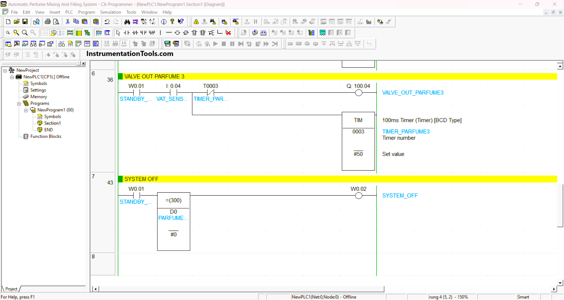
RUNG 7 (SYSTEM OFF)
When the NO contact of memory bit STANDBY_MODE (W0.01) in HIGH state and the value in memory word PERFUME_WEIGHT (D0) is equal to zero “0”, then the memory bit SYSTEM_OFF (W0.02) changes to HIGH state.
Read Next:
- Automatic Vacuum Cleaner PLC Programming
- STAR-DELTA Auto And Manual PLC Program
- Electric Motor Forward Reverse PLC Logic
- Product Painting with Omron PLC Program
- Attendance System Program in Omron PLC