Inst ToolsInst ToolsInst Tools
  • Ask
  • Courses
  • Videos
  • Q & A
    • Interview
      • Instrumentation
      • Electronics
      • Electrical
      • Practical Questions
    • MCQ
      • Instrumentation MCQ
      • Electrical MCQ
      • Electronics MCQ
      • Control Systems MCQ
      • Analog Electronics MCQ
      • Digital Electronics MCQ
      • Power Electronics MCQ
      • Microprocessor MCQ
      • Multiple Choice Questions
  • EE
    • Electronics
      • Electronics Q & A
      • Electronic Basics
      • Electronic Devices & Circuits
      • Electronics Animation
      • Digital Electronics
    • Electrical
      • Electrical Basics
      • Electrical Q & A
      • Power Electronics
      • Electrical Machines
      • Electrical Animation
      • Power Systems
      • Switchgear & Protection
      • Transmission & Distribution
  • Measure
    • Control Valves
    • Calibration
    • Temperature
    • Pressure
    • Flow
    • Level
    • Analyzers
    • Switches
    • Vibration
    • Solenoid Valve
  • Control
    • PLC Tutorials
    • Control Systems
    • Safety Instrumented System (SIS)
    • Communication
    • Fire & Gas System
  • More
    • Design
    • Tools
    • Animation
    • Basics
    • Formulas
    • Standards
    • TextBooks
    • Common
    • Software
    • Excel Tools
    • Erection & Commissioning
    • Process Fundamentals
    • Videos
    • Books
Search
All rights reserved. Reproduction in whole or in part without written permission is prohibited.
Reading: Measure Flow rate using Level Sensors
Share
Notification Show More
Font ResizerAa
Inst ToolsInst Tools
Font ResizerAa
  • Courses
  • PLC Tutorials
  • Control Systems
Search
  • Ask
  • Courses
  • Videos
  • Q & A
    • Interview
    • MCQ
  • EE
    • Electronics
    • Electrical
  • Measure
    • Control Valves
    • Calibration
    • Temperature
    • Pressure
    • Flow
    • Level
    • Analyzers
    • Switches
    • Vibration
    • Solenoid Valve
  • Control
    • PLC Tutorials
    • Control Systems
    • Safety Instrumented System (SIS)
    • Communication
    • Fire & Gas System
  • More
    • Design
    • Tools
    • Animation
    • Basics
    • Formulas
    • Standards
    • TextBooks
    • Common
    • Software
    • Excel Tools
    • Erection & Commissioning
    • Process Fundamentals
    • Videos
    • Books
Follow US
All rights reserved. Reproduction in whole or in part without written permission is prohibited.
Inst Tools > Blog > Flow Measurement > Measure Flow rate using Level Sensors

Measure Flow rate using Level Sensors

Level sensors are capable of measuring more than just level. Flow rate measurement in an open channel can be accomplished using weirs and flumes.

Last updated: November 1, 2023 5:51 am
Editorial Staff
Flow Measurement
No Comments
Share
2 Min Read
SHARE

Level sensors are capable of measuring more than just level. Flow rate measurement in an open channel, such as a stream, irrigation canal, or unpressurized sewerage pipe, can be accomplished using hydraulic structures known as weirs and flumes.

These measure flow rates using the same technologies often applied to tank-level measurements, such as bubblers, radar, and ultrasonic level transmitters.

Level Sensors Measure Flow

Both weirs and flumes function by constricting the flow of the channel and measuring how the fluid level is affected.

Their physical characteristics, and therefore their effect on fluid flow, are known variables, so equipment that measures the level upstream from the structure can use a series of mathematical equations to determine the flow rate.
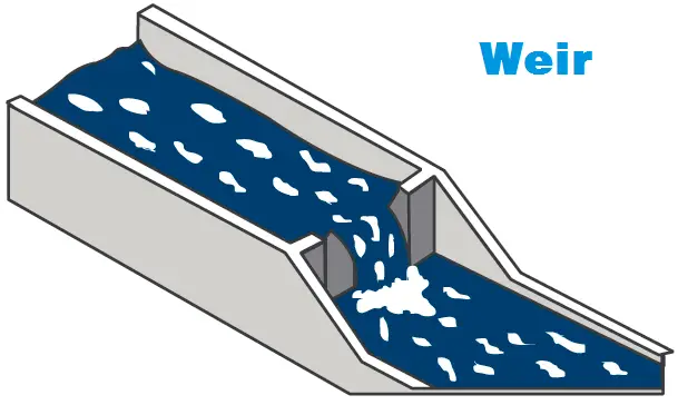
Weir Flow Meter Principle

Weirs function very similarly to dams in that they span the length of the channel and constrict the flow.

There are many styles of weirs, each meant for a different application, but they all allow fluid to escape through an opening and continue downstream. The fluid level is measured upstream from the weir.
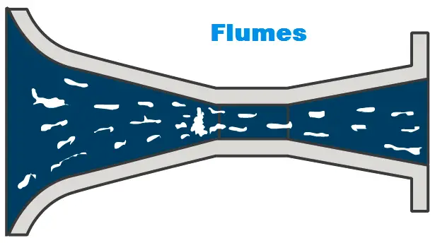
Flumes Flow Meter Principle

Flumes, on the other hand, typically consist of three sections: a constricting end, a throat, and an expanding end. The flume is partially submerged in the channel. The throat constricts the flow and the fluid level is measured at the constricting end.

If you liked this article, then please subscribe to our YouTube Channel for Instrumentation, Electrical, PLC, and SCADA video tutorials.

You can also follow us on Facebook and Twitter to receive daily updates.

Read Next:

  • Flow Transmitters Questions
  • Velocity Flow Meter Principle
  • Flow Control Loop Controller 
  • DP Flow Transmitter Measure
  • Float Switch Working Principle
Don't Miss Our Updates
Be the first to get exclusive content straight to your email.
We promise not to spam you. You can unsubscribe at any time.
Invalid email address
You've successfully subscribed !
Standardized Volumetric Flow
What are Multiphase Flow Meters? – Working Principle, Advantages
Orifice Flow Meters: Detailed Specifications
Impulse Line – Purpose & Tapping Point Location
What is Integral Flow Orifice Assembly?
Share This Article
Facebook Whatsapp Whatsapp LinkedIn Copy Link
Share
Leave a Comment

Leave a Reply Cancel reply

Your email address will not be published. Required fields are marked *

Stay Connected

128.3kFollowersLike
69.1kFollowersFollow
208kSubscribersSubscribe
38kFollowersFollow

Categories

Recent Comments

  • Kamli on Top Free PLC Software
  • Guifty Shimica on Top Non-PLC Certification Courses for Automation Professionals
  • Guifty Shimica on Top Non-PLC Certification Courses for Automation Professionals
  • MIHARITSOA Aina Sitraka on Top Non-PLC Certification Courses for Automation Professionals

Related Articles

Measuring Instruments

Flow Instruments – Selection, Principle & Application

Square root extractor Parts

What is a Square Root Extractor? – DP Flow Measurement

Turbine Flow Meter Installation Procedure

What is a K Factor

Flow Meter K-factor and Calculations

Flow Meter Calibration Procedure

Flow Meter Calibration

Flow Measurement

Continuous Flow Measurement

orifice plate vent hole

What is the Purpose of Orifice Plate Drain Hole and Vent Hole?

Rotameter

What is a Variable Area Flow Meter?

More Articles

Single Line Diagram

Single Line Diagram

Why Fiber Optic Cable is Spliced rather than Termination

Why Fiber Optic Cable is Spliced rather than Termination?

Distributed IO for Siemens PLC

How to Configure Distributed IO in a PLC Project?

Ultrasonic Flow Meters Working Principle

Ultrasonic Flow Meters Working Principle

Logic Gates and Truth tables

Logic Gates and Truth tables

PLC IO Examples

Quiz: Identifying I/O Examples in PLC Systems

Control Systems Questions & Answers

Control Systems Objective Questions & Answers – Set 2

Calibration Procedure of displacer type Level transmitter

Calibration of Displacer Level Transmitter

Follow US
All rights reserved. Reproduction in whole or in part without written permission is prohibited.
Welcome Back!

Sign in to your account

Username or Email Address
Password

Lost your password?