Inst ToolsInst ToolsInst Tools
  • Courses
  • Videos
  • Q & A
    • Interview
      • Instrumentation
      • Electronics
      • Electrical
      • Practical Questions
    • MCQ
      • Instrumentation MCQ
      • Electrical MCQ
      • Electronics MCQ
      • Control Systems MCQ
      • Analog Electronics MCQ
      • Digital Electronics MCQ
      • Power Electronics MCQ
      • Microprocessor MCQ
      • Multiple Choice Questions
  • EE
    • Electronics
      • Electronics Q & A
      • Electronic Basics
      • Electronic Devices & Circuits
      • Electronics Animation
      • Digital Electronics
    • Electrical
      • Electrical Basics
      • Electrical Q & A
      • Power Electronics
      • Electrical Machines
      • Electrical Animation
      • Power Systems
      • Switchgear & Protection
      • Transmission & Distribution
  • Measure
    • Control Valves
    • Calibration
    • Temperature
    • Pressure
    • Flow
    • Level
    • Analyzers
    • Switches
    • Vibration
    • Solenoid Valve
  • Control
    • PLC Tutorials
    • Control Systems
    • Safety Instrumented System (SIS)
    • Communication
    • Fire & Gas System
  • More
    • Design
    • Tools
    • Animation
    • Basics
    • Formulas
    • Standards
    • TextBooks
    • Common
    • Software
    • Excel Tools
    • Erection & Commissioning
    • Process Fundamentals
    • Videos
    • Books
Search
All rights reserved. Reproduction in whole or in part without written permission is prohibited.
Reading: What is Pump Redundancy?
Share
Notification Show More
Font ResizerAa
Inst ToolsInst Tools
Font ResizerAa
  • Courses
  • PLC Tutorials
  • Control Systems
Search
  • Courses
  • Videos
  • Q & A
    • Interview
    • MCQ
  • EE
    • Electronics
    • Electrical
  • Measure
    • Control Valves
    • Calibration
    • Temperature
    • Pressure
    • Flow
    • Level
    • Analyzers
    • Switches
    • Vibration
    • Solenoid Valve
  • Control
    • PLC Tutorials
    • Control Systems
    • Safety Instrumented System (SIS)
    • Communication
    • Fire & Gas System
  • More
    • Design
    • Tools
    • Animation
    • Basics
    • Formulas
    • Standards
    • TextBooks
    • Common
    • Software
    • Excel Tools
    • Erection & Commissioning
    • Process Fundamentals
    • Videos
    • Books
Follow US
All rights reserved. Reproduction in whole or in part without written permission is prohibited.
Inst Tools > Blog > Process Fundamentals > What is Pump Redundancy?

What is Pump Redundancy?

Pump redundancy is a system where only one pump works at a time, which is called a working pump. There may be two or more pumps.

Last updated: April 17, 2023 3:43 pm
Viral Nagda
Process Fundamentals
No Comments
Share
5 Min Read
SHARE

When you use pumps in an application, there are two major types of control in it. Control in the sense refers here to a set of two pumps for example.

Contents
What is Pump Redundancy?Pump Redundancy Methods

In the first type, both pumps will run and in the second type, only one pump will run. These are the most commonly used types of controls for pumps and other types of motors. When we come to the second type of control, it is easier to operate the pumps. This type of control is also called pump redundancy control.

In this post, we will learn the concept of pump redundancy.

What is Pump Redundancy?

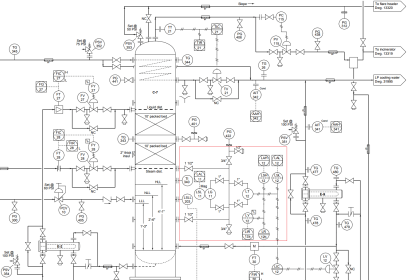
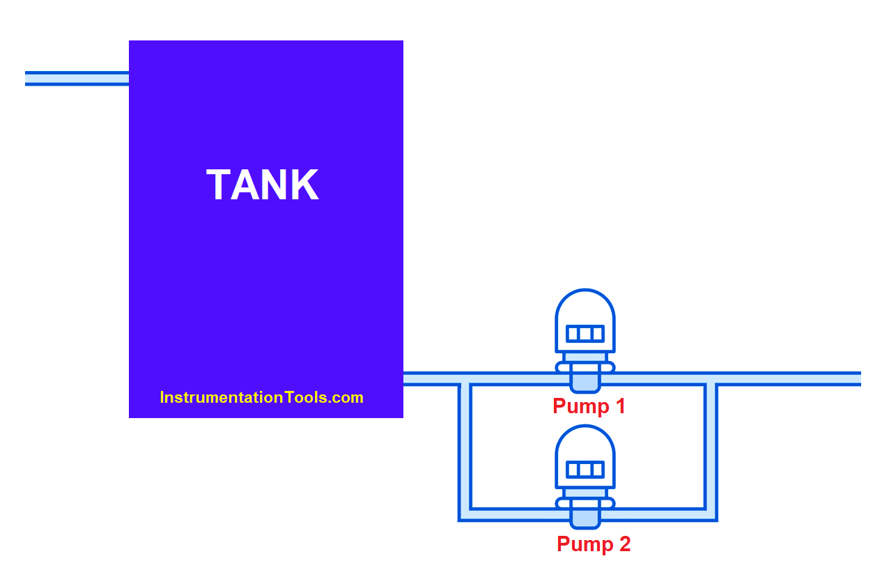
In industrial automation, you have many applications where a set of two pumps are present. Refer to the below image for understanding the concept. As you can see, two pumps are connected to the tank, but the output of the pump is a common discharge line.

Now, with this construction, you can have the two types of controls as discussed earlier. Let us understand the second type of control now for the redundancy of the pumps.

What is Pump Redundancy

The outlet will normally have a pressure or flow transmitter connected. This will be used to regulate the flow of liquid from the pump. If you designed the system in such a way that only one pump will fulfill the demands, then this technique of redundancy will be required to run the system.

Pump redundancy is a system where only one pump works at a time, which is called a working pump. There may be 2 or more pumps. When the pump trips or if its working hours are achieved, then the standby pump will start. Due to this method, only one pump will thus run at a time and fulfill the demands of the user.

Pump Redundancy Methods

In pump redundancy, there are various controls to select the working or standby pump. The first one is manual selection. Suppose you want to run pump-2. Then, the operator will manually select the pump-2 in system off condition first. When selected, the user will start the system. Once started, pump-2 will thus run and achieve the pressure or flow demands.

The second condition to select a pump is by working hours. Continuing with the above example, suppose pump-2 is running in the system. Now, you have set a time of 8 hours for each pump to run. If pump-2 is running continuously for 8 hours, then pump-2 will stop and after a small delay, pump-1 will start running. Then, the cycle will repeat for pump-1; which will also check it for 8 hours.

The third condition for selecting a pump is by checking the trip conditions. Continuing with the above example, suppose pump-1 is running in the system. Now, if pump-1 trips during the running conditions, then pump-1 will stop, and after a small delay, pump-2 will start running. Then, the cycle will repeat for pump-2; which will also check it for any trip condition.

These are the three methods through which pump redundancy works. You can thus work with only one pump with full automation control. This way, you can achieve energy efficiency, motor working balance, and lifetime improvement in devices.

If you liked this article, then please subscribe to our YouTube Channel for Instrumentation, Electrical, PLC, and SCADA video tutorials.

You can also follow us on Facebook and Twitter to receive daily updates.

Read Next:

  • Cybersecurity in PLC
  • Actuator Sensor Interface
  • PLC, HMI, VFD, and Motor
  • Virtual Reality in Automation
  • Car Wash Logic using PLC
Don't Miss Our Updates
Be the first to get exclusive content straight to your email.
We promise not to spam you. You can unsubscribe at any time.
Invalid email address
You've successfully subscribed !

Continue Reading

Concept of Desuperheater
Centrifugal Compressor near ½-RPM Frequency High Magnitude Shaft Vibrations
Why Counter-current Heat Exchangers are better than Co-current?
Process Control Fundamentals
Deep-Bed Filters
Rotary Compressors
Share This Article
Facebook Whatsapp Whatsapp LinkedIn Copy Link
Share
Leave a Comment

Leave a Reply Cancel reply

Your email address will not be published. Required fields are marked *

Stay Connected

128.3kFollowersLike
69.1kFollowersFollow
208kSubscribersSubscribe
38kFollowersFollow

Categories

Explore More

Introduction to Wastewater Treatment Works and Pumping Station
Ball Float Steam Trap
Components of Water Treatment Plant
Heat Exchanger Root Cause Analysis (RCA)
Gas Compressor Seal Oil System
Flare Knockout Drums Working Animation
Plant Air Storage Tank Pressure Fluctuations Root Cause Analysis
CO2 Absorber Corroded Wall Thickness & Weld Building
What is a Y Strainer ?
Process Control High Level Alarm Fault Analysis

Keep Learning

Mechanical Strainers

Strainers

Precoat Filters

Precoat Filters

What is a Dosing Pump? - Types, Advantages, Applications

What is a Dosing Pump? – Types, Advantages, Applications

Chemical Dosing Control System

Introduction to Chemical Dosing System

Industrial Gases

Questions and Answers on Gas

Circulating Pump

What is a Circulating Pump?

Instrument Air (IA) System

Process Design of Instrument Air System

Steam Turbine Driven Centrifugal Compressors Leak due to Broken Instrument

Steam Turbine Driven Centrifugal Compressors Leak due to Broken Instrument

Discover More

PLC Programming Projects for Beginners

PLC Programming Projects for Beginners

Burst Transformers Root Cause Analysis

Root Cause Analysis – Burst Transformers and 11 kV Input Breakers

Time Response Analysis

State Variable Analysis – Part I

EPC Questions and Answers

EPC Questions and Answers

Determine Resistance value of Resistors

Determine Resistance value of Resistors

Rolled & Seal Welded Tube to Tube sheet joints

Gas Cooler Re-tubing Done Successfully (Root Cause Analysis)

Schneider PLC Programming Example

Schneider PLC Programming Example for Beginners

Types of Pressure Measuring Scales

Types of Pressure Measuring Scales

Follow US
All rights reserved. Reproduction in whole or in part without written permission is prohibited.
Welcome Back!

Sign in to your account

Username or Email Address
Password

Lost your password?