Pneumatic systems are simpler than hydraulic and electric systems, conferring advantages in upfront costs and maintenance.
Fluid power systems produce linear motion with simple pneumatic and hydraulic cylinders and actuators. Converting electrical to linear power often requires one or more mechanical devices to convert the motor rotation.
Pneumatic and hydraulic power transmission methods typically produce more power in a smaller space, so small pneumatic cylinders can be used to provide the high required clamping or positioning force needed to hold a product in certain machining and other applications.
Control of this power is usually easier with pneumatics and hydraulics than with electric systems. A simple valve, regulator and flow controls are usually all that’s needed to control cylinder direction, speed, and force.
An electric actuator often needs an electronic controller, multiple I/O points, communication cables, and possibly encoder feedback, along with more complex automation system programming.
Pneumatic Handbook
This pneumatic handbook consists of 13 chapters as mentioned in the below table.
| Chapter 1 | Why Use Pneumatics |
| Chapter 2 | Pneumatic Circuit Symbols Explained |
| Chapter 3 | Understanding Pneumatic Air Preparation |
| Chapter 4 | Pneumatic Actuator (Air Cylinder) Basics |
| Chapter 5 | Valves for Pneumatic Cylinders | Actuators |
| Chapter 6 | Pneumatic Tubing & Hose |
| Chapter 7 | Pneumatic Fittings |
| Chapter 8 | Are Pneumatic Components Compatible |
| Chapter 9 | Electro-pneumatic Systems in Action Sensors |
| Chapter 10 | Pneumatic System Design Considerations Sensors |
| Chapter 11 | Energy Efficient Pneumatic Systems |
| Chapter 12 | Pneumatic Actuator vs. Electromechanical |
| Chapter 13 | Application Stories |
A pneumatic actuator typically has two very repeatable end-of-travel positions which are set by using a hard stop, cushion, or shock. Electric actuators are also very repeatable and can be easily designed with multiple stop positions.
With new advances in electronics, pneumatic control of multiple stop positions is also now possible although not as precise as electric can be. Whether it is end-of-stroke or multiple stop positions, both pneumatic, and electrical actuators can attain the desired position at high speeds.
Operation of a compressor may have additional costs compared to electric, but the availability of clean dry air in most facilities is common.
In addition, pneumatic components often have the lowest maintenance costs, such as when replacing seals, or a whole cylinder for that matter, which is often much cheaper than servicing, let alone replacing, an electric actuator.
Noise is becoming less of a concern with fluid power devices. Designs have improved over the years, greatly reducing clatter to about the same level as a stepper-driven electric actuator.
New improvements in designs and efficiency of compressors, and the standard use and distribution of clean dry air in a manufacturing facility, also make pneumatics a good choice for industrial automated machinery.
Difference between Pneumatic, Hydraulic, and Electrical
| Characteristics | Pneumatic | Hydraulic | Electrical |
|---|---|---|---|
| Complexity | Simple | Medium | Medium/High |
| Peak power | High | Very high | High |
| Size | Low size/force | Very low size/force | Medium size/force |
| Control | Simple valves | Simple valves | Electronic controller |
| Position accuracy | Good | Good | Better |
| Speed | Fast | Slow | Fast |
| Purchase cost | Low | High | High |
| Operating cost | Medium | High | Low |
| Maintenance cost | Low | High | Low |
| Utilities | Compressor/power/ pipes | Pump/ power/ pipes | Power only |
| Efficiency | Low | Low | High |
| Reliability | Excellent | Good | Good |
| Maintenance | Low | Medium | Medium |
Basic Pneumatic System
All pneumatic systems will have certain basic components. The first is a compressor, and then a system to distribute the clean, dry air it produces.
The common pneumatic components on automated machines include:
- air preparation system (shut-off/lock-out, combination filter/regulator, soft start valve)
- control valves and manifolds (manual, air pilot, solenoid-operated)
- air cylinders and actuators
- tubing and hoses
- push-to-connect fittings
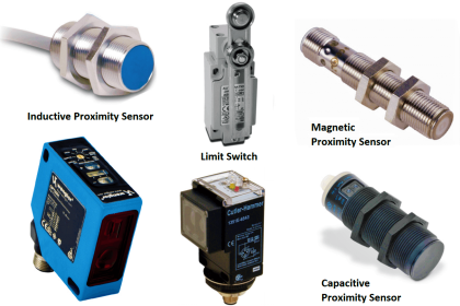
- cylinder position sensors
- discrete pressure switches
- specialty components and accessories
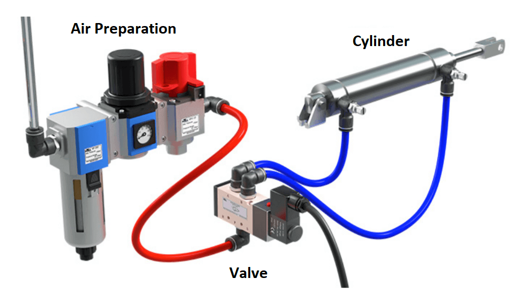
Since most facilities have a plant air supply, the machine pneumatic system starts with the air preparation unit to which the plant air is connected. The air prep system should include a manual and lockable shutoff valve, filter, water trap, and pressure regulator.
An electrically operated soft start might also be considered to remove air during an emergency stop, guard open, or similar safety event. The air prep system may also include a lubricator, but it’s usually not necessary unless pneumatic rotary tools are in use.
The air prep system typically feeds the valves or valve manifold that can include manual, air-piloted, and solenoid operated control valves to turn the air supply off and on. These valves feed control air to a variety of pneumatic cylinders and actuators where power transmission happens.
Pneumatic cylinder position sensors and pressure switches are common components in pneumatic systems.
There are also a wide variety of special pneumatic components such as flow controls, quick exhaust valves, hand valves, check valves, inline pressure regulators, gauges, and indicators.
| Title: | Pneumatic Handbook and Practical Guide |
| Author: | Automation Direct |
| Format: | |
| Size: | 3.69 MB |
| Pages: | 62 |
| Download: | Click Here |
If you liked this article, then please subscribe to our YouTube Channel for Instrumentation, Electrical, PLC, and SCADA video tutorials.
You can also follow us on Facebook and Twitter to receive daily updates.
Read Next:
- Electrical Enclosure Book
- Control Valve Basics Book
- Industrial Control System Book
- Download Instrumentation Books
- Industrial Sensors Practical Book


I need the on my email
I need ref book for pneumatic automation projects
Greetings, I’m glad to be with you people so as to have more knowledge on pneumatic. I do it locally here in Africa and I will like to improve on it.
I’m installing a ride well air lift single bag system on a 50 ton Talbert trailer and cannot find assistance from either corporate entity’s. Any help available would be greatly appreciated.