A pressure control valve is used to regulate or maintain the required pressure in a process control loop.
Also, Fluid pressure control valves protect the system against the overpressure conditions that may occur either on the account of gradual buildup due to a decrease in fluid or sudden surge due to opening or closing of valves.
Pressure surges can be rapid and sudden, increase as much as four times the normal system pressure and that is the reason why pressure control devices are essential in any hydraulic circuit.
Types of Pressure Control Valves
Pressure control valves that act to regulate pressure in a circuit may be divided into the following ways.
- Pressure relief valve,
- Counterbalance valve and
- Sequence valve.
Pressure relief, pressure reducing, sequence loading, counterbalance valves control the gradual buildup of pressure in a hydraulic system.
Pressure Relief valve
Pressure relief in a hydraulic circuit can be done in the following ways.
- Direct operated pressure relief valve
- Pilot operated pressure relief valve
Direct Operated Pressure Relief Valve
The most extensively used type of pressure control valve is the pressure relief valve.
A pressure relief valve is generally used to restrict the maximum pressure developed in a hydraulic system and is set at a higher pressure than the normal working pressure needed.
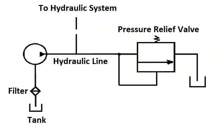
A pressure relief valve is normally a closed valve, and its purpose is to restrict the pressure to a set maximum value by diverting the pump flow back to the tank.
The primary port of a relief valve is connected to system pressure and the secondary port connects to the directional control valve and to the tank.
When the poppet in the relief valve is pushed at a certain pressure, a connection is established between the primary and secondary ports resulting in the flow getting diverted to the tank.
By direct force, a mechanical spring holds the poppet inside the valve. The spring is usually adjustable.
The knob is used to set the spring tension so that the poppet is kept closed. It will be adjusted to the desired pressure range. The poppet moves upwards only when the system pressure reached the cracking pressure.
When the hydraulic pressure does not accept any flow due to a safety reason in the system, the pressure relief valve delivers the fluid back to the tank to maintain continuously the desired system pressure in the hydraulic circuit. It provides protection counter to any overloads experienced by the actuators in the hydraulic system.
One important function of a pressure relief valve is a limitation of the torque or force produced by the hydraulic motors or cylinders.
Pilot Operated Pressure Relief Valve
A pressure relief valve is one that operates in two stages. They are designed to fit in with higher pressures than direct-acting relief valves at the same flow rate capacity.
Pilot operated relief valve comprises two stages, in the first stage of the pilot relief valve comprises a main spool which is normally closed and kept in a hold position by a non-adjustable spring.
The pilot is located in the upper valve body and contains a pressure limiting poppet.
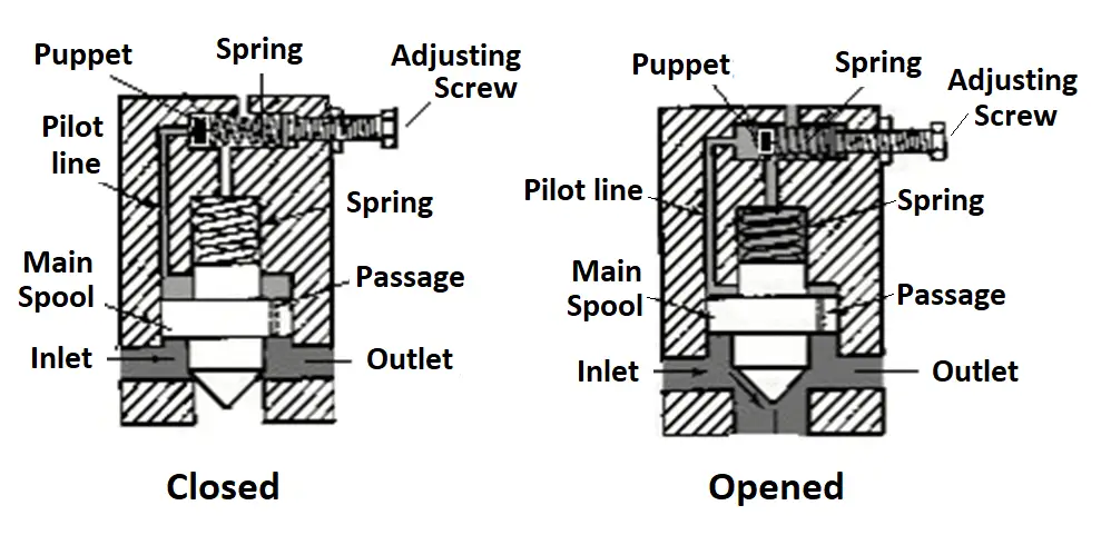
As soon as the pressure attains the setting of the adjustable spring, the poppet in the second stage is forced to move off from its seat. This limits the pressure in the upper chamber.
The restricted flow is very little and then passes through the orifice into the upper chamber results in an increase in pressure in the lower chamber. This causes an imbalance in the hydraulic forces. Which tends to release the piston off its seat.
When the pressure difference between the upper and the lower chamber reaches approximately 1.5 kg/cm2 the large piston lifts off its eat to permit flow directly to the tank.
The advantage with pilot operated pressure relief valve is that in certain applications it is required to operate at less pressure compared to the direct-operated pressure relief valve.
Counterbalance Valve
A Counterbalance valve is used to avoid uncontrolled movement of the cylinder.
When raising the cylinder, an integral check valve opens in order to permit a free flow for retraction of the cylinder.
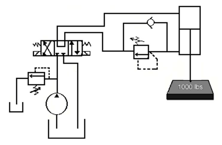
The figure is an example of how exactly the counterbalance valve operates in a hydraulic circuit. As can be seen in the figure, the counterbalance valve is placed just after the cylinder in order to avoid any uncontrolled operation.
In case if the counterbalance valve is not provided, there would be an uncontrollable fall of the load, something which the pump flow would find hard to keep pace with.
The counterbalance valve is set to a pressure somewhat higher than the load-induced pressure. As the cylinder is extended, there must be a slight increase in pressure so as to drive the load down.
Sequence Valve
A sequence valve is used to ascertain that a certain pressure level is attained in one branch of the circuit before a second branch is activated.
A sequence control valve is used to perform two operations in sequence one after the other. For example, first, cylinder-1 will extend and later cylinder-2 will extend.
A sequence valve is closely resembled the pressure relief valve and is used where a set of operations are to be controlled in a pressure-related sequence manner.
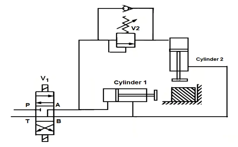
The figure above shows a distinctive example where a workpiece is pushed into a position by cylinder-1 and clamped by cylinder-2.
Sequence valve V2 is connected to the extended line of cylinder-1. When this cylinder’s piston is moving the workpiece, the line pressure is low but gets rises once the workpiece hits the end stop.
The sequence valve opens once its inlet pressure rises above a certain set level. Cylinder-2 operates to clamp the workpiece. A check valve across V2 permits both cylinders to retract together.
The sequence is achieved between the two cylinders.
Reference: Hydraulics and Pneumatics a Technician’s and Engineers guide by Andrew Parr.
If you liked this article, then please subscribe to our YouTube Channel for Instrumentation, Electrical, PLC, and SCADA video tutorials.
You can also follow us on Facebook and Twitter to receive daily updates.
Read Next:


I have been so great full for the bit theoretical knowledge??