In this post, we will cover the basic concepts of the safety relay.
One of the most important components used in an electrical panel is a relay. A relay is an electromechanical switch that is electrically energized to operate its mechanical contacts. Basically, it separates two circuits and works as a contact between them.
Basics of Relay
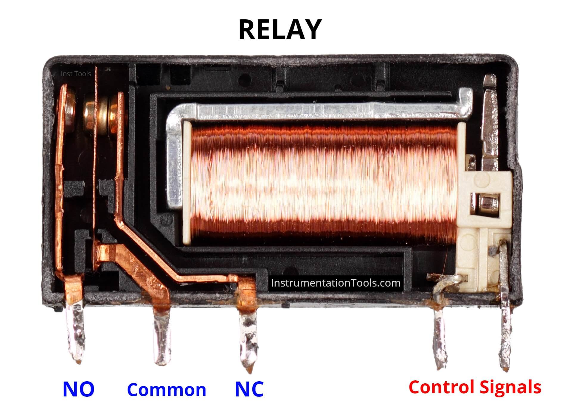
Refer to the below image. A standard relay consists of 5 terminals.
The input circuit consists of two terminals – positive potential and negative potential.
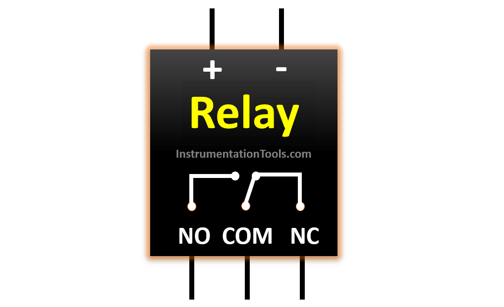
The output circuit consists of three terminals – common (COM), normally-Open (NO), and normally-Closed (NC).
In de-energized condition, the contact is between COM and NC terminals. When the coil is energized, the contact is between COM and NO terminals. This is the basic concept of a relay.
This normal relay protects both the circuits from damaging each other.
For example, if any issue occurs on the input side, then only the input circuit will be affected. No damage would happen on the outputs side.
But, in today’s advances in automation and instrumentation, the safety of the environment and electrical components is a crucial factor in designing the system.
In a normal relay, as mechanical contacts are used, they may weld or jam with each other after repeated cycle operation.
It is a rare condition but if the safety of the panel and system is a main criterion, then a normal relay would prove dangerous in this situation. It will happen like the coil is energized, but the contacts have not switched.
So suppose if an emergency stop contact is used at the input side and the output side is connected to a PLC input, then the contact will not be detected and the system will thus not stop, even if the switch is pressed.
Many European and American standards avoid the use of a standard relay in their control panel.
Safety Relay
For this condition, a safety relay is used. A safety relay is more advanced and technical in operation as compared to a normal relay. This ensures that it can be used for a fail-safe environment.
Safety relays are defined and made to satisfy various SIL (Safety Integrity Levels) applications.
Let us see some of its highlights:
A safety relay has an in-built self-monitoring feature. That means, if the contacts weld or get jammed, the relay will automatically turn off the circuit contact at both the input and output sides.
This happens because the correct opening and closing of these relays are tested automatically inside it in each on-off cycle. This ensures that the safety function works even in case of its internal components failure.
Safety relays can detect fault at the input circuit during a fault.
They are generally used in combination with various safety relays or you can say in multiple numbers; which guarantees a completely safe environment for the operator to use the machine.
A safety relay is generally used for critical field devices which require hardcore safety monitoring, like
- light curtains,
- safety mats,
- three-position devices,
- two-hand control devices,
- magnetic switches,
- emergency stop buttons,
- non-contact safety sensors,
- interlock safety switches etc.
Some relays have a reset button in it, much like overload relays. This ensures that the operator will first identify and rectify the faults, and then press the button to again bring it into operation.
Nowadays, they also have communication ports integrated with them (Ethernet, Modbus, etc.) to exchange electrical data with the PLC or other control equipment.
One of the main distinguishing factors from a normal relay are it’s forcibly guided contacts.
That means, even are the contacts are going into a weld or jam condition, they are forcibly and mechanically guided to change their position; so that the problem does not occur.
This ensures that both the NO and NC contacts always work opposite with each other; as in normal operation.
Choosing a safety relay requires a sound knowledge of risk assessment factors and technology. ISO 12100 is normally used for this.
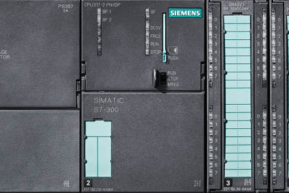
In industrial automation, we mostly have a PLC that is essential for system control but it does not inherently ensure safety. Safety measures, such as safety relays, safety PLCs, and proper safety programming, must be implemented to protect personnel and equipment.
So, if we use safety relays instead of a normal relay, the features discussed earlier will ensure a very safe environment; or you can say we can get a double safe environment.
Safety relays can detect wire breaks, faulty contactors, faulty safety actuators, short circuits, etc.
A safety relay detects wire breaks and faulty contactors/actuators by sending out electrical pulses through the wiring. By measuring the flow of current, the safety relay checks for welded contact sets and wire breaks.
Author: Viral Nagda
If you liked this article, then please subscribe to our YouTube Channel for Instrumentation, Electrical, PLC and SCADA video tutorials.
You can also follow us on Facebook and Twitter to receive daily updates.
Read Next:


very much informative post…thank you very much.
The article has some very useful information and I don’t want to overlook this. It is benefical and has some good reference material. However, I felt compelled to address one point that was mentioned.
The article states, “In automation, if there is PLC, then there is no need to worry about safety. The program written will ensure all the equipment is operated properly.” This is absolutely NOT true.
Safety Relays and Safety Controllers are engineered and manufactured such that if they fail the safety circuit opens, thereby stopping the operations of equipment.
A software engineer could have an error in their code that could allow unsafe operations of equipment. Also, Input and Output circuits of the PLC could become defective, again, thereby allowing unsafe operations of equipment.
Great article. Easy to understand. I also agree with the previous comment from Mr. McCoy. PLCs are not inherently safe, but must be programmed to be safe. Adding a safety PLC in addition to a safety relay can add additional safe-guards.