Desuperheater Design types which are fixed and variable geometry nozzle, self contained, steam atomized, and geometry assisted wafer.
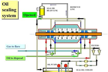
Desuperheater Design
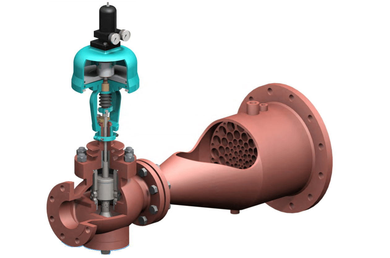
Image Courtesy: Auldvalves
Fixed Geometry Nozzle Design
The fixed geometry nozzle design is a simple mechanically atomized desuperheater with single or multiple fixed geometry spray nozzles.
It is intended for applications with nearly constant load changes (rangeability up to 5:1) and is capable of proper atomization in steam flow velocities as low as 14 feet per second under optimum conditions
Standard installation of this type of unit is through a flanged branch connection tee on a 6-inch or larger steam pipe line. This design is usually not available for large Cv requirements. This unit requires an external water control valve to meter water flow based on a signal from a temperature sensor in the downstream steam line.
Variable Geometry Nozzle Design
The variable geometry nozzle design is also a simple mechanically atomized desuperheater, but it employs one or more variable geometry, back pressure activated spray nozzles.
Due to the variable geometry, this unit can handle applications requiring control over moderate load changes (rangeability up to 20:1) and is capable of proper atomization in steam flow velocities as low as 14 feet per second under optimum conditions.
Standard installation of this type of unit is through a flanged branch connection tee on an 8-inch or larger steam pipe line. These units are available for large Cv requirements. This design requires an external water control valve to meter water flow based on a signal from a temperature sensor in the downstream steam line.
Self Contained Design
The self-contained design is also mechanically atomized with one or more variable geometry, back pressure activated spray nozzles.
As a special feature, this unit incorporates a water flow control element that performs the function normally provided by an external water control valve. This control element has a plug that moves inside a control cage by means of an actuator, which receives a signal from a temperature sensor in the downstream steam line.
The water flow then passes to the variable geometry nozzle(s) and is atomized as it enters the steam pipe line. Because of the close coordination of the intrinsic control element and the variable geometry nozzle(s), this unit can handle applications requiring control over moderate to high load changes (rangeability up to 25:1).
It offers proper atomization in steam flow velocities as low as 14 feet per second under optimum conditions. Standard installation of this type of unit is through a flanged branch connection tee on an 8-inch or larger steam pipe line. These are available for moderate Cv requirements.
Steam Atomized Design
The steam atomized design incorporates the use of high-pressure steam for rapid and complete atomization of the spraywater. This is especially useful in steam pipe lines that have low steam velocity.
The atomizing steam, usually twice the main steam line pressure or higher, encounters the water in the spray nozzle chamber where the energy of the expanding atomizing steam is used to atomize the water into very small droplets.
These smaller droplets allow for faster conversion to steam and permit the water to remain suspended in a low steam velocity flow, thereby allowing complete vaporization to occur.
The steam atomized design, therefore, can properly mix water into steam flow velocities as low as approximately 4 feet per second (1.2 meters per second) under optimum conditions. This design handles applications requiring very high load changes (rangeability up to 50:1).
Standard installation of this type of unit is through a flanged branch connection tee on an 8-inch or larger steam pipe line. This design is available for moderate Cv requirements.
It requires an external water control valve to meter water flow based on a signal from a temperature sensor in the downstream steam line. This system also requires a separate on/off valve for the atomizing steam supply.
Geometry Assisted Wafer Design
The geometry-assisted wafer design was originally developed for small steam pipe line sizes of less than 6-inch that were unable to accommodate an insertion style desuperheater.
The unit is designed as a wafer that is installed between two flanges in the steam pipe line. A reduced diameter throat venturi allows water to spray completely around the wafer and permits multiple points of spraying either through drilled holes or small nozzles.
In addition, the venturi increases the steam velocity at the point of injection, which enhances atomization and mixing in steam flow velocities as low as approximately 10 feet per second (3 meters per second) under optimum conditions. It handles applications requiring control over moderate load change (rangeability up to 20:1).
It can be installed in steam pipe line sizes of 1-inch through 24-inch, and is available for moderate Cv requirements. This design requires an external water control valve to meter water flow based on a signal from a temperature sensor in the downstream steam line.
Also Read: What is a Desuperheater?