Inst ToolsInst ToolsInst Tools
  • Courses
  • Videos
  • Q & A
    • Interview
      • Instrumentation
      • Electronics
      • Electrical
      • Practical Questions
    • MCQ
      • Instrumentation MCQ
      • Electrical MCQ
      • Electronics MCQ
      • Control Systems MCQ
      • Analog Electronics MCQ
      • Digital Electronics MCQ
      • Power Electronics MCQ
      • Microprocessor MCQ
      • Multiple Choice Questions
  • EE
    • Electronics
      • Electronics Q & A
      • Electronic Basics
      • Electronic Devices & Circuits
      • Electronics Animation
      • Digital Electronics
    • Electrical
      • Electrical Basics
      • Electrical Q & A
      • Power Electronics
      • Electrical Machines
      • Electrical Animation
      • Power Systems
      • Switchgear & Protection
      • Transmission & Distribution
  • Measure
    • Control Valves
    • Calibration
    • Temperature
    • Pressure
    • Flow
    • Level
    • Analyzers
    • Switches
    • Vibration
    • Solenoid Valve
  • Control
    • PLC Tutorials
    • Control Systems
    • Safety Instrumented System (SIS)
    • Communication
    • Fire & Gas System
  • More
    • Design
    • Tools
    • Animation
    • Basics
    • Formulas
    • Standards
    • TextBooks
    • Common
    • Software
    • Excel Tools
    • Erection & Commissioning
    • Process Fundamentals
    • Videos
    • Books
Search
All rights reserved. Reproduction in whole or in part without written permission is prohibited.
Reading: Difference between LVDT and RVDT?
Share
Notification Show More
Font ResizerAa
Inst ToolsInst Tools
Font ResizerAa
  • Courses
  • PLC Tutorials
  • Control Systems
Search
  • Courses
  • Videos
  • Q & A
    • Interview
    • MCQ
  • EE
    • Electronics
    • Electrical
  • Measure
    • Control Valves
    • Calibration
    • Temperature
    • Pressure
    • Flow
    • Level
    • Analyzers
    • Switches
    • Vibration
    • Solenoid Valve
  • Control
    • PLC Tutorials
    • Control Systems
    • Safety Instrumented System (SIS)
    • Communication
    • Fire & Gas System
  • More
    • Design
    • Tools
    • Animation
    • Basics
    • Formulas
    • Standards
    • TextBooks
    • Common
    • Software
    • Excel Tools
    • Erection & Commissioning
    • Process Fundamentals
    • Videos
    • Books
Follow US
All rights reserved. Reproduction in whole or in part without written permission is prohibited.
Inst Tools > Blog > Common > Difference between LVDT and RVDT?

Difference between LVDT and RVDT?

LVDT stands for linear voltage differential transformer, whereas RVDT stands for rotary voltage differential transformer.

Last updated: September 28, 2022 2:38 pm
R Jagan Mohan Rao
Common
2 Comments
Share
4 Min Read
SHARE

LVDT and RVDT is a passive transducer. LVDT stands for linear voltage differential transformer, whereas RVDT stands for rotary voltage differential transformer.

Contents
LVDTRVDTDifference between LVDT and RVDT

It is an inductive transducer converts displacement into a change in inductance of the coil.
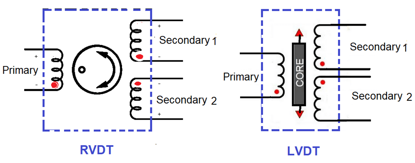
Difference between LVDT and RVDT

LVDT

The Linear voltage differential transformer converts linear displacement into an electrical signal. It comprises one primary and two secondary coil windings. Both windings are an equal number of turns and they are connected in series to each other. The primary winding is placed as opposed to the two secondary windings as shown in the below figure.

The primary winding is excited by the alternating current, the core is placed inside of it. The alternating current induces flux in primary and by mutual induction, the flux is induced in secondary.

LVDT stands for linear voltage differential transformer

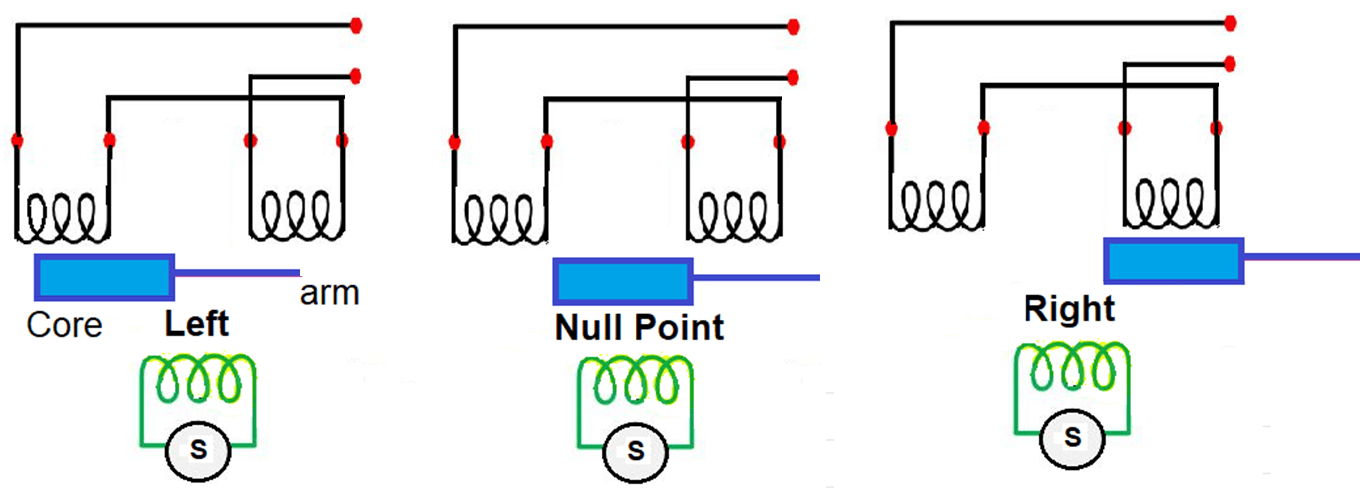
Induced flux changes in secondary windings as per the movement of the iron core at the null position, left-hand side, and right side.

RVDT

The rotary variable differential transformer used for the measurement of angular displacement. It converts angular displacement into an alternating electrical signal. The construction of RVDT and LVDT are similar, in both cases one primary winding and two secondary windings are used.

The only difference is that core in RVDT is cam-shaped and rotated inside the windings through a shaft attached to it. The core is rotated in a clockwise and anti-clockwise rotation with respect to a NULL position.

When the core is in the null position, the output voltage is zero and because the voltages induced in both secondary windings S1 and S2 are equal and opposite direction. If any angular displacement is measured to be applied to the core, differential voltages get developed across the windings S1 and S2.

When the core is rotated in a clockwise direction, the voltage gets an increase. Voltages get decreased when rotated in an anti-clockwise direction.

Difference between LVDT and RVDT

  • LVDT – converts linear displacements into alternating electrical signals.
  • RVDT – converts angular displacements into alternating electrical signals.
  • LVDT – core is in linear motion.
  • RVDT – core is circular.
  • LVDT – used for converting linear motions into electrical signals.
  • RVDT – used for converting rotary motions into electrical signals.
  • LVDT – Linear over displacement up to several hundred millimeters long.
  • RVDT – It operates 360 degrees but the range of linear operation is + or – 40 degrees.
  • LVDT – Core shape is rectangular.
  • RVDT – Core is cam-shaped.
  • LVDT –  Input voltage range from 1V to 24 V RMS.
  • RVDT – Upto 3 V RMS.
  • LVDT – Sensitivity 2.3 mV/V/ degree of rotation.
  • RVDT – Sensitivity 2 to 3 mV/ V/ degree of rotation.
  • LVDT – Operating frequency range from 50 Hz to 20 kHz.
  • RVDT – Operating frequency range from 400 Hz to 20 kHz.
  • LVDT – Its application in measuring force, pressure, weight, displacement.
  • RVDT – Used in various precision controlling applications such as turbine operation, radar systems, etc.

Reference: MECHATRONICS By M.D Singh J.P Joshi.

Read Next:

  • History of Instrument Signals
  • Compare Fieldbus & 4-20mA
  • Why 4-20 mA Popular?
  • What is Live Zero in 4-20 mA?
  • Loop Checking of Transmitters
Don't Miss Our Updates
Be the first to get exclusive content straight to your email.
We promise not to spam you. You can unsubscribe at any time.
Invalid email address
You've successfully subscribed !

Continue Reading

Which HVAC System is Best for Home?
FPGA vs. CPLD – What are the differences between them
Pirani Gauge Working Principle
Pneumatic Cylinder Movement Control with Timer Circuit
Difference Between Microcontroller and Microprocessor
Hazard Identification & Risk Assessment (HIRA)
Share This Article
Facebook Whatsapp Whatsapp LinkedIn Copy Link
Share
2 Comments
  • OLUGBENGA TAIWO says:
    December 3, 2022 at 2:44 pm

    THIS IS GREAT. KEEP UP THE GOOD WORK.
    GOD BLESS YOU SIR

    Reply
    • Parshu says:
      December 4, 2022 at 2:43 pm

      Good

      Reply

Leave a Reply Cancel reply

Your email address will not be published. Required fields are marked *

Stay Connected

128.3kFollowersLike
69.1kFollowersFollow
208kSubscribersSubscribe
38kFollowersFollow

Categories

Explore More

Understanding the Chiller Maintenance – HVAC Tutorials
Strip Chart Recorder Working Principle
HVAC Valves
List of 100 Sensors and Transducers Questions
Industrial Automation Controls used in HVAC
Five Types of PCB Assembly that You Should Know
Mechanical Torsion Meter Principle
Pneumatic Load Cell Principle
5 Ways CNC Machining is Benefiting the Glass Industry
Good and Bad Wiring Practices

Keep Learning

wash column temperature control

Pneumatic Instrumentation

Career Scope in Electrical Engineering

Career Scope in Electrical Engineering

What is Optical Coating

What is Optical Coating?

Pressure Regulator with Flapper-Nozzle Principle

Pressure Regulator with Flapper-Nozzle Principle

Displacement Sensing Accelerometer

Seismic Displacement Sensing Accelerometer

Instrumentation documents

Instrumentation documents

Vision Camera System

Vision Camera Systems in Industrial Automation

Do You Need a VPN on Your Home Computer?

Do You Need a VPN on Your Home Computer?

Discover More

Configure the Instruments in Flow Control Loop

Configure the Instruments in Flow Control Loop

RFID Based Projects for Engineering Students

RFID Projects for Engineering Students

Keyphasor Principle

What is Keyphasor ? How does Keyphasor works ?

DP Transmitter Wet Leg Compensating Impulse Line

Questions on DP Transmitter Wet Leg Compensating Impulse Line

Siemens PLC programming: BCD, Integer, Double Integer, Real

Diaphragm Valves

How Diaphragm Valves Work ?

Control System Vendor Internal Test Procedures

Vendor View of Supplying Industrial Process Control & Safety Systems

Electrical Machines Questions and Answers

Transformer Open Circuit and Short Circuit Test

Follow US
All rights reserved. Reproduction in whole or in part without written permission is prohibited.
Welcome Back!

Sign in to your account

Username or Email Address
Password

Lost your password?