Inst ToolsInst ToolsInst Tools
  • Ask
  • Courses
  • Videos
  • Q & A
    • Interview
      • Instrumentation
      • Electronics
      • Electrical
      • Practical Questions
    • MCQ
      • Instrumentation MCQ
      • Electrical MCQ
      • Electronics MCQ
      • Control Systems MCQ
      • Analog Electronics MCQ
      • Digital Electronics MCQ
      • Power Electronics MCQ
      • Microprocessor MCQ
      • Multiple Choice Questions
  • EE
    • Electronics
      • Electronics Q & A
      • Electronic Basics
      • Electronic Devices & Circuits
      • Electronics Animation
      • Digital Electronics
    • Electrical
      • Electrical Basics
      • Electrical Q & A
      • Power Electronics
      • Electrical Machines
      • Electrical Animation
      • Power Systems
      • Switchgear & Protection
      • Transmission & Distribution
  • Measure
    • Control Valves
    • Calibration
    • Temperature
    • Pressure
    • Flow
    • Level
    • Analyzers
    • Switches
    • Vibration
    • Solenoid Valve
  • Control
    • PLC Tutorials
    • Control Systems
    • Safety Instrumented System (SIS)
    • Communication
    • Fire & Gas System
  • More
    • Design
    • Tools
    • Animation
    • Basics
    • Formulas
    • Standards
    • TextBooks
    • Common
    • Software
    • Excel Tools
    • Erection & Commissioning
    • Process Fundamentals
    • Videos
    • Books
Search
All rights reserved. Reproduction in whole or in part without written permission is prohibited.
Reading: Instrument Cable Voltage Drop
Share
Notification Show More
Font ResizerAa
Inst ToolsInst Tools
Font ResizerAa
  • Courses
  • PLC Tutorials
  • Control Systems
Search
  • Ask
  • Courses
  • Videos
  • Q & A
    • Interview
    • MCQ
  • EE
    • Electronics
    • Electrical
  • Measure
    • Control Valves
    • Calibration
    • Temperature
    • Pressure
    • Flow
    • Level
    • Analyzers
    • Switches
    • Vibration
    • Solenoid Valve
  • Control
    • PLC Tutorials
    • Control Systems
    • Safety Instrumented System (SIS)
    • Communication
    • Fire & Gas System
  • More
    • Design
    • Tools
    • Animation
    • Basics
    • Formulas
    • Standards
    • TextBooks
    • Common
    • Software
    • Excel Tools
    • Erection & Commissioning
    • Process Fundamentals
    • Videos
    • Books
Follow US
All rights reserved. Reproduction in whole or in part without written permission is prohibited.
Inst Tools > Blog > Basics > Instrument Cable Voltage Drop

Instrument Cable Voltage Drop

Last updated: May 29, 2020 9:55 am
Editorial Staff
Basics
No Comments
Share
2 Min Read
SHARE

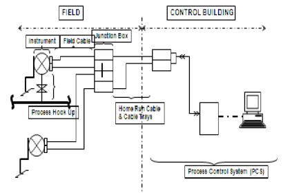
Sizing of instrument cable should be performed to ensure that instrument device such as solenoid valve and its cabling works properly.

There are two factors that should be checked i.e. voltage drop and current carrying capacity.

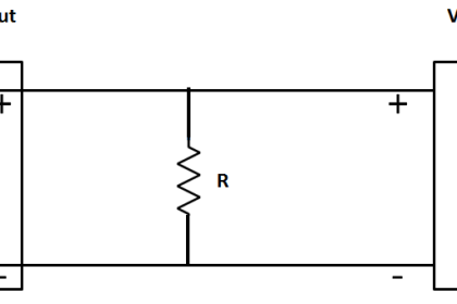
Voltage drop is calculated as follows:

Instrument Cable Voltage Drop

where:

Rio = Input resistance of I/O Card (Ohm)
Rw = Resistance of wire at specified temperature per lenght (Ohm/m)
Rins = Resistance of instrument device (Ohm)
L = Length of cable / distance from instrument to cabinet in control room (m)
In = Load current (A), obtained from power consumption of instrument device divided by power supply voltage.

Rins, Rio and Rw can be obtained from manufacturer’s catalog for instrument, I/O card and cable respectively.

The cable suits the application if calculated voltage drop is less than maximum permissible voltage drop by the system.

Current Carrying Capacity of a certain cable is defined as the maximum current that can flow through a cable without melting the conductor or insulation. Current Carrying Capacity varies depending on several factors such as conductor size, ambient temperature, and cable installation.

These factors are referred as derating factors and IEC has established the values for each.The cable suits the application if nominal current (In) is less than current carrying capacity.

Read Next:

  • Introduction to Diodes
  • Digital Memory Concepts
  • Valve Safety Factor
  • Instrument Air Design
  • Delta-Sigma ADC

Source: instrument-control blog

Don't Miss Our Updates
Be the first to get exclusive content straight to your email.
We promise not to spam you. You can unsubscribe at any time.
Invalid email address
You've successfully subscribed !
Basics of Valves
Difference between Transmitter and Transducer with Examples
What is Process Control?
Difference between Smart Transmitter and Ordinary Transmitter
Process Control Fundamentals
Share This Article
Facebook Whatsapp Whatsapp LinkedIn Copy Link
Share
Leave a Comment

Leave a Reply Cancel reply

Your email address will not be published. Required fields are marked *

Stay Connected

128.3kFollowersLike
69.1kFollowersFollow
208kSubscribersSubscribe
38kFollowersFollow

Categories

Recent Comments

  • Guifty Shimica on Top Non-PLC Certification Courses for Automation Professionals
  • Guifty Shimica on Top Non-PLC Certification Courses for Automation Professionals
  • MIHARITSOA Aina Sitraka on Top Non-PLC Certification Courses for Automation Professionals
  • Vaishnavi on Free Instrumentation Course for Trainee Engineers

Related Articles

Relay Internal Parts

Relay Operation, Types, Symbols & Characteristics

Difference Between Sensor and Transducer

What is the Difference Between Sensor and Transducer?

Instrument Linearity Error

Instrument Errors – Zero, Span, Linearity

Instrumentation Abbreviations

Instrumentation Abbreviations

Two wire loop powered transmitters

4-20 mA Transmitter Wiring Types : 2-Wire, 3-Wire, 4-Wire

Instrumentation Logic Checks

How to Do Logic Checks During Plant Pre-Commissioning

Why 4-20 mA Current Signal is used instead of Voltage Signal

Troubleshooting a 4-20mA Current loop

Resistor-Color-Code-Chart

Resistor Color Code Animation

More Articles

SCR Full Bridge Converter

Power Electronics – Full-wave Rectifier With R and RL Load

Zigzag Transformers Theory

Zigzag Transformers Theory

Allen Bradley PLC communication is established

Procedure for Connecting Allen Bradley PLC and PC – RS Logix 500

Wrongly terminated Thermocouple (TC) wires

Too Low-Temperature Readings after a Failed Thermocouple Change

Power System Protection and Relays Questions & Answers

Power System Protection and Relays Questions & Answers

Safety Questions and Answers

Safety Questions and Answers

Resistor Y and Delta Network Calculation

Y and Delta Resistor Network Calculations

Why does SMPS Need isolation - Switch Mode Power Supply

Why does SMPS Need isolation? – Switch Mode Power Supply

Follow US
All rights reserved. Reproduction in whole or in part without written permission is prohibited.
Welcome Back!

Sign in to your account

Username or Email Address
Password

Lost your password?