Inst ToolsInst ToolsInst Tools
  • Ask
  • Courses
  • Videos
  • Q & A
    • Interview
      • Instrumentation
      • Electronics
      • Electrical
      • Practical Questions
    • MCQ
      • Instrumentation MCQ
      • Electrical MCQ
      • Electronics MCQ
      • Control Systems MCQ
      • Analog Electronics MCQ
      • Digital Electronics MCQ
      • Power Electronics MCQ
      • Microprocessor MCQ
      • Multiple Choice Questions
  • EE
    • Electronics
      • Electronics Q & A
      • Electronic Basics
      • Electronic Devices & Circuits
      • Electronics Animation
      • Digital Electronics
    • Electrical
      • Electrical Basics
      • Electrical Q & A
      • Power Electronics
      • Electrical Machines
      • Electrical Animation
      • Power Systems
      • Switchgear & Protection
      • Transmission & Distribution
  • Measure
    • Control Valves
    • Calibration
    • Temperature
    • Pressure
    • Flow
    • Level
    • Analyzers
    • Switches
    • Vibration
    • Solenoid Valve
  • Control
    • PLC Tutorials
    • Control Systems
    • Safety Instrumented System (SIS)
    • Communication
    • Fire & Gas System
  • More
    • Design
    • Tools
    • Animation
    • Basics
    • Formulas
    • Standards
    • TextBooks
    • Common
    • Software
    • Excel Tools
    • Erection & Commissioning
    • Process Fundamentals
    • Videos
    • Books
Search
All rights reserved. Reproduction in whole or in part without written permission is prohibited.
Reading: Questions on Pressure Transmitter Calibration Setup
Share
Notification Show More
Font ResizerAa
Inst ToolsInst Tools
Font ResizerAa
  • Courses
  • PLC Tutorials
  • Control Systems
Search
  • Ask
  • Courses
  • Videos
  • Q & A
    • Interview
    • MCQ
  • EE
    • Electronics
    • Electrical
  • Measure
    • Control Valves
    • Calibration
    • Temperature
    • Pressure
    • Flow
    • Level
    • Analyzers
    • Switches
    • Vibration
    • Solenoid Valve
  • Control
    • PLC Tutorials
    • Control Systems
    • Safety Instrumented System (SIS)
    • Communication
    • Fire & Gas System
  • More
    • Design
    • Tools
    • Animation
    • Basics
    • Formulas
    • Standards
    • TextBooks
    • Common
    • Software
    • Excel Tools
    • Erection & Commissioning
    • Process Fundamentals
    • Videos
    • Books
Follow US
All rights reserved. Reproduction in whole or in part without written permission is prohibited.
Inst Tools > Blog > Pressure Measurement > Questions on Pressure Transmitter Calibration Setup

Questions on Pressure Transmitter Calibration Setup

Last updated: May 22, 2020 6:47 pm
Editorial Staff
Pressure Measurement Practical Questions
1 Comment
Share
1 Min Read
SHARE

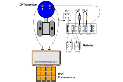
Determine what will happen at the following steps in the sequence (when prompted for a response) in this pressure transmitter calibration setup:

Contents
Pressure Transmitter Calibration SetupStep 1:Step 2:Step 3:Step 4:Step 5:Step 6:Step 7:Step 8:Answer:Read Next:

Pressure Transmitter Calibration Setup

pressure transmitter calibration setup

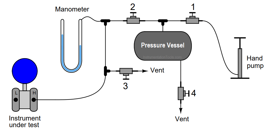
The sequence of steps as follows:

Step 1:

Open valves 1 and 2

Step 2:

Close valves 3 and 4

Step 3:

Operate hand pump until manometer registers maximum pressure

Step 4:

Quickly open and close valve 4 – does the manometer indication drop greatly, slightly, or not at all?

Step 5:

Close valve 2

Step 6:

Quickly open and close valve 4 – does the manometer indication drop greatly, slightly, or not at all?

Step 7:

Close valve 1

Step 8:

Quickly open and close valve 3 – does the manometer indication drop greatly, slightly, or not at all?

Answer:

Step 4: Manometer indication drops slightly

Step 6: Manometer indication does not drop at all

Step 8: Manometer indication drops greatly

Read Next:

  • Calibration of Pressure Transmitter
  • Loop Powered Pressure Transmitter
  • Water Filter Discharge Pressure Gauge
  • Differential Pressure Transmitter Questions
  • PLC Calculation for Pressure Transmitter
  • Installation of Pressure Transmitter
Don't Miss Our Updates
Be the first to get exclusive content straight to your email.
We promise not to spam you. You can unsubscribe at any time.
Invalid email address
You've successfully subscribed !
Troubleshoot Allen Bradley PLC Logic
Pressure Transmitter Manifolds
Closed Tank Remote Seal Capillary type DP Transmitter
Define Normal Status for each of the Process Switch
Differential Capacitance Pressure Sensor Circuit
Share This Article
Facebook Whatsapp Whatsapp LinkedIn Copy Link
Share
1 Comment
  • Ramón says:
    May 24, 2020 at 9:23 pm

    Its a very nice exercise, thanks.

    Reply

Leave a Reply Cancel reply

Your email address will not be published. Required fields are marked *

Stay Connected

128.3kFollowersLike
69.1kFollowersFollow
208kSubscribersSubscribe
38kFollowersFollow

Categories

Recent Comments

  • Kamli on Top Free PLC Software
  • Guifty Shimica on Top Non-PLC Certification Courses for Automation Professionals
  • Guifty Shimica on Top Non-PLC Certification Courses for Automation Professionals
  • MIHARITSOA Aina Sitraka on Top Non-PLC Certification Courses for Automation Professionals

Related Articles

Draw the Symbols for Liquid Level Measuring Instruments

Draw the Symbols for Liquid Level Measuring Instruments

Measuring process vessel clogging

DP Transmitter Applications

Limit Switches Wiring

Draw Limit Switch Symbol ?

U tube Manometer Working

Basics of Pressure

Allen-Bradley MicroLogix 1000 PLC

Questions on Allen-Bradley MicroLogix 1000 PLC

Difference between Absolute, Gauge and Differential Pressure Transmitters

Difference between Absolute, Gauge and Differential Pressure Transmitters

Baffle Nozzle Assembly Sensitive Mechanism

Baffle Nozzle Assembly Sensitive Mechanism

Absolute and Gauge Pressure

Difference Between Absolute and Gauge Pressure

More Articles

What is Transformer Bushing

What is Transformer Bushing? Working Principle

Ion Spectrometers Questions & Answers

Ion Spectroscopy Questions & Answers

Typical Switchyard Layout

Electrical Substation – Busbar Arrangements and Layouts

4-20mA Current Loop Components

Why Use a Current Loop?

Asynchronous Motor Animation

Asynchronous Motor Animation

PLC Interlock Example

PLC Interlock Logic with First Input Priority

Closed Tank Level Measurement using DP Transmitter

Cat and Mouse type Level Indicator

Free WinCC SCADA Training Course

Free SCADA Training Course

Follow US
All rights reserved. Reproduction in whole or in part without written permission is prohibited.
Welcome Back!

Sign in to your account

Username or Email Address
Password

Lost your password?