Inst ToolsInst ToolsInst Tools
  • Ask
  • Courses
  • Videos
  • Q & A
    • Interview
      • Instrumentation
      • Electronics
      • Electrical
      • Practical Questions
    • MCQ
      • Instrumentation MCQ
      • Electrical MCQ
      • Electronics MCQ
      • Control Systems MCQ
      • Analog Electronics MCQ
      • Digital Electronics MCQ
      • Power Electronics MCQ
      • Microprocessor MCQ
      • Multiple Choice Questions
  • EE
    • Electronics
      • Electronics Q & A
      • Electronic Basics
      • Electronic Devices & Circuits
      • Electronics Animation
      • Digital Electronics
    • Electrical
      • Electrical Basics
      • Electrical Q & A
      • Power Electronics
      • Electrical Machines
      • Electrical Animation
      • Power Systems
      • Switchgear & Protection
      • Transmission & Distribution
  • Measure
    • Control Valves
    • Calibration
    • Temperature
    • Pressure
    • Flow
    • Level
    • Analyzers
    • Switches
    • Vibration
    • Solenoid Valve
  • Control
    • PLC Tutorials
    • Control Systems
    • Safety Instrumented System (SIS)
    • Communication
    • Fire & Gas System
  • More
    • Design
    • Tools
    • Animation
    • Basics
    • Formulas
    • Standards
    • TextBooks
    • Common
    • Software
    • Excel Tools
    • Erection & Commissioning
    • Process Fundamentals
    • Videos
    • Books
Search
All rights reserved. Reproduction in whole or in part without written permission is prohibited.
Reading: Pressure Transmitter Animation
Share
Notification Show More
Font ResizerAa
Inst ToolsInst Tools
Font ResizerAa
  • Courses
  • PLC Tutorials
  • Control Systems
Search
  • Ask
  • Courses
  • Videos
  • Q & A
    • Interview
    • MCQ
  • EE
    • Electronics
    • Electrical
  • Measure
    • Control Valves
    • Calibration
    • Temperature
    • Pressure
    • Flow
    • Level
    • Analyzers
    • Switches
    • Vibration
    • Solenoid Valve
  • Control
    • PLC Tutorials
    • Control Systems
    • Safety Instrumented System (SIS)
    • Communication
    • Fire & Gas System
  • More
    • Design
    • Tools
    • Animation
    • Basics
    • Formulas
    • Standards
    • TextBooks
    • Common
    • Software
    • Excel Tools
    • Erection & Commissioning
    • Process Fundamentals
    • Videos
    • Books
Follow US
All rights reserved. Reproduction in whole or in part without written permission is prohibited.
Inst Tools > Blog > Animation > Pressure Transmitter Animation

Pressure Transmitter Animation

Last updated: November 22, 2018 9:10 pm
Editorial Staff
Animation How It Works Pressure Measurement
19 Comments
Share
2 Min Read
SHARE
Pressure Transmitter Working Animation
Pressure Transmitter Animation

Animation Credits : Siemens

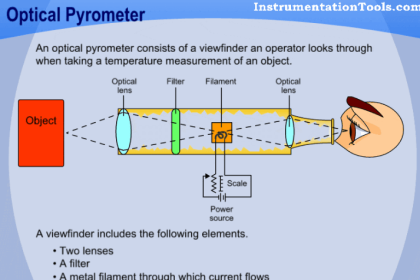
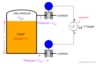
Pressure Transmitter Working Principle:

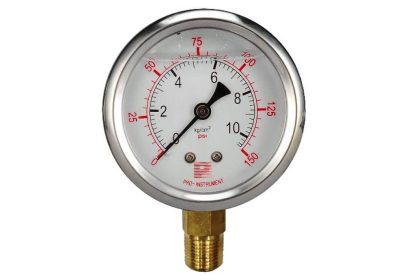
When we apply pressure to the Pressure Transmitter, then the applied pressure acts as a force on the diaphragm inside the pressure transmitter. Then the diaphragm either expands or compress depends on the applied pressure.


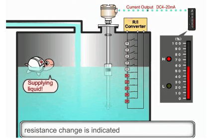
Diaphragm expand or compress basis on positive or negative pressure. The resistors are mounted on top of the diaphragm. So when the diaphragm expands or compress, the resistance value changes. These resistors are connected in a standard Wheatstone bridge. The change in resistance is measured using a Wheatstone bridge. The bridge output is proportional to applied pressure.


Note: In Some types of pressure transmitters manufactures can use capacitance, inductance, conductivity, piezo electric crystals etc in place of resistors. So depending on the applied pressure the diaphragm expands or compress, then respective sensor parameter like resistance, capacitance, inductance, piezo electric crystal etc.. will change and it is proportional to the pressure.

Finally this is all I could do in this tutorial and I hope it is simple enough to understand for newbies too.

If you’re facing any kind of problem or need any help regarding understanding of Pressure Transmitters then just leave your message in the comments or shoot me an email. Your feedback is much appreciated.


I’ll definitely get back to support you. Support me by sharing this post and socializing with me. 🙂

Also See :
Non-Contact Radar Level Transmitter Animation
Probe Type Radar Level Transmitter Animation
Ultrasonic Level Transmitter Animation 


Don't Miss Our Updates
Be the first to get exclusive content straight to your email.
We promise not to spam you. You can unsubscribe at any time.
Invalid email address
You've successfully subscribed !
Effects of Symmetric and Asymmetric Capillary Tube Pressure Measurement
Microwave Barrier Level Switch Working Principle
Thermistor Working Principle
Unbonded Strain Gauge Principle
Potentiometer Working Principle Animation
Share This Article
Facebook Whatsapp Whatsapp LinkedIn Copy Link
Share
19 Comments
  • Akbar says:
    June 15, 2015 at 4:21 pm

    Excellent Explanation using Pressure Transmitter Animation…. Dude !!!

    Reply
  • San says:
    June 16, 2015 at 6:55 am

    Awesome Animation @ Good Work.

    Reply
  • dheeraj dhawas says:
    March 17, 2016 at 8:55 am

    Dear sir,

    amazing explanation, but tell me about wheatstone bridge so that i can fully Understand.

    Reply
  • Varsha says:
    April 20, 2016 at 4:38 am

    Excellant explanation Mr. Reddy.

    Reply
  • ajaz sheikh says:
    May 10, 2016 at 4:54 pm

    How to calibrate pressure tx

    Reply
  • behram baloch says:
    May 18, 2016 at 5:44 am

    excellent also plz explain working principle wheatstone bridge how goes signal to dcs or plc what changes

    Reply
  • Hi tenders mishra says:
    June 13, 2016 at 4:13 pm

    Sir how pizo electric transducer pressure transmitter works.

    Reply
  • pradeep kumar says:
    July 21, 2016 at 1:26 pm

    Respected sir ,
    i am very thank full for giving most valuable information with good animation and explanation and also i am requesting you plz explain how to calibrate to absolute pressure transmitter of range -1 to 1.5 kg/sqr cm. Thanking u sir

    Reply
  • Bhavin Bhimani says:
    November 12, 2016 at 9:22 am

    Sir I hv some questions regarding level transmitter,
    How can work submersible level transmitter and how can we mount it and is it suitable for measuring level in canpiping??

    Reply
  • Asad says:
    November 12, 2016 at 9:51 am

    Slam
    Sir Can U show a electronic Circuit of capacitance and piezo electric type pressure transmitter with a pressure Applying Animation.

    Reply
  • jitendra meena says:
    July 25, 2017 at 10:15 am

    very very useful for new join instrumentation engineer. we appreciate your hard work to the website. thank you sir

    Reply
  • Muthukumar Murugan says:
    November 8, 2017 at 12:32 pm

    We are using Pressure Transmitter (Yokogawa Transmitter). Range from 5 bar to 100 bar.
    It was located in Compressor discharge line (30″ Line).
    Pressure Transmitter Operation Range up to 72 Barg. It is communicating via Profibus with Siemens PCS7 System.
    When Compressor running that pressure transmitter giving spike of more that 100 bar for 10 seconds. That over range is tripping system.

    Do you have any idea. Problem in transmitter Or PCS7 system. Please advice..

    Reply
    • kuthbudeen ibrahim says:
      November 11, 2017 at 5:54 am

      check the intial current of the compressor. this high amount of pressure only displayed on 10 sec.plz check the compressor if u have any gauge in that line check the gauge pressure also

      Reply
  • manish wadia says:
    January 28, 2018 at 6:37 am

    thank,s you…sir for yours ..kind of support at the level inside of the instrumentation,,,, thanx again

    Reply
  • Moin Uddin Ahmed. says:
    March 27, 2018 at 9:22 am

    Dear Sir,
    Thank You for Your kind effort & co-operation. I am expecting a suggestion from You. Say I am using a Differential Pressure Transmitter for measuring Pressure, Level Or Flow. Output of Differential Pressure Transmitter is 4-20 mA but I want to display it directly on Monitor not in the om of mA rather Pressure or Flow.. So have any configureable Display ? So that I can recognize it 4mA means certain pressure & 20 mA means another certain pressure & it will follow equation like y=mx +c. It will also record the Data of specified time (after 10 minutes interval it will record & send) & it will send it to another computer through internet.

    Reply
  • Mohammad. Irshad says:
    May 3, 2018 at 7:09 pm

    Dear Sir,

    I really appreciate your work. Thank you for your kind support to us.

    Please provide us more and more information about Instrumentation and cover the practical points of view those peoples are working in Industrial instrumentation. your information is really needed.

    Thanking you once again.
    Regards,
    Mohammad. Irshad Mallick

    Reply
  • Rico Lasmarias says:
    June 26, 2018 at 11:10 am

    when i blow off either high side or low pressure side of my transmitter for cleaning the pipe line due to mud water my remote water level indicator does not work as normal before.

    Reply
  • Mohammed says:
    November 22, 2018 at 3:25 am

    Thanks a lot for your illustrations …
    If I want to convert these signals that produced by sensor (4-20ma) to Ethernet signal to transmit it to another location by antenna ,so what I need or work to do that …

    Reply
  • satish says:
    December 13, 2019 at 12:34 pm

    Dear sir,

    amazing explanation, but tell me about wheatstone bridge so that i can fully Understand

    Reply

Leave a Reply Cancel reply

Your email address will not be published. Required fields are marked *

Stay Connected

128.3kFollowersLike
69.1kFollowersFollow
208kSubscribersSubscribe
38kFollowersFollow

Categories

Recent Comments

  • Kamli on Top Free PLC Software
  • Guifty Shimica on Top Non-PLC Certification Courses for Automation Professionals
  • Guifty Shimica on Top Non-PLC Certification Courses for Automation Professionals
  • MIHARITSOA Aina Sitraka on Top Non-PLC Certification Courses for Automation Professionals

Related Articles

Radiometric level Principle

Radiometric level measurement Working Principle

Bubbler Level Measurement Animation

Bubbler Level Measurement Animation

Helix and Spiral Tubes - Pressure Sensor

Helix and Spiral Tubes – Pressure Sensor

Argonite Fire Suppression System Animation

Argonite Fire Suppression System Working Principle

Strain Gauge Pressure Sensor Principle

Strain Gauge Pressure Sensor Principle

Oscillating Piston Flow Meters Animation

Oscillating Piston Flow Meters Working Principle

Switch NO or NC Contact

Normally-open and Normally-closed Switch Contacts

Deluge Valve Operation using Solenoid Valve Animation

Deluge Valve Operation

More Articles

RSLogix5000 PLC Program Backup procedure

Control Valve Plug Stem and Gland Leaks

Repeat Control Valve Plug Stem and Gland Leaks

LBB protection relay

What is the LBB Protection Relay? (Local Breaker Backup)

NIST Traceability

NIST Traceability

How to Select a pH and ORP Meter

How to Select a pH or ORP Meter

Solenoid Valve Troubleshooting

Solenoid Valve Troubleshooting Tips

Hazard Identification and Risk Assessment

Hazard Identification & Risk Assessment (HIRA)

Paddle Wheel Flow Meter

Paddle Wheel Flow Meters – Principle, Advantages, Limitations

Follow US
All rights reserved. Reproduction in whole or in part without written permission is prohibited.
Welcome Back!

Sign in to your account

Username or Email Address
Password

Lost your password?