Inst ToolsInst ToolsInst Tools
  • Courses
  • Automation
    • PLC
    • Control System
    • Safety System
    • Communication
    • Fire & Gas System
  • Instrumentation
    • Design
    • Pressure
    • Temperature
    • Flow
    • Level
    • Vibration
    • Analyzer
    • Control Valve
    • Switch
    • Calibration
    • Erection & Commissioning
  • Interview
    • Instrumentation
    • Electrical
    • Electronics
    • Practical
  • Q&A
    • Instrumentation
    • Control System
    • Electrical
    • Electronics
    • Analog Electronics
    • Digital Electronics
    • Power Electronics
    • Microprocessor
  • Request
Search
  • Books
  • Software
  • Projects
  • Process
  • Tools
  • Basics
  • Formula
  • Power Plant
  • Root Cause Analysis
  • Electrical Basics
  • Animation
  • Standards
  • 4-20 mA Course
  • Siemens PLC Course
Reading: Identify the Purpose of Flow Ratio Controller
Share
Font ResizerAa
Inst ToolsInst Tools
Font ResizerAa
  • Courses
  • Design
  • PLC
  • Interview
  • Control System
Search
  • Courses
  • Automation
    • PLC
    • Control System
    • Safety System
    • Communication
    • Fire & Gas System
  • Instrumentation
    • Design
    • Pressure
    • Temperature
    • Flow
    • Level
    • Vibration
    • Analyzer
    • Control Valve
    • Switch
    • Calibration
    • Erection & Commissioning
  • Interview
    • Instrumentation
    • Electrical
    • Electronics
    • Practical
  • Q&A
    • Instrumentation
    • Control System
    • Electrical
    • Electronics
    • Analog Electronics
    • Digital Electronics
    • Power Electronics
    • Microprocessor
  • Request
Follow US
All rights reserved. Reproduction in whole or in part without written permission is prohibited.
Inst Tools > Blog > Practical Questions > Identify the Purpose of Flow Ratio Controller

Identify the Purpose of Flow Ratio Controller

Last updated: March 7, 2020 9:02 am
Editorial Staff
Practical Questions
No Comments
Share
1 Min Read
SHARE

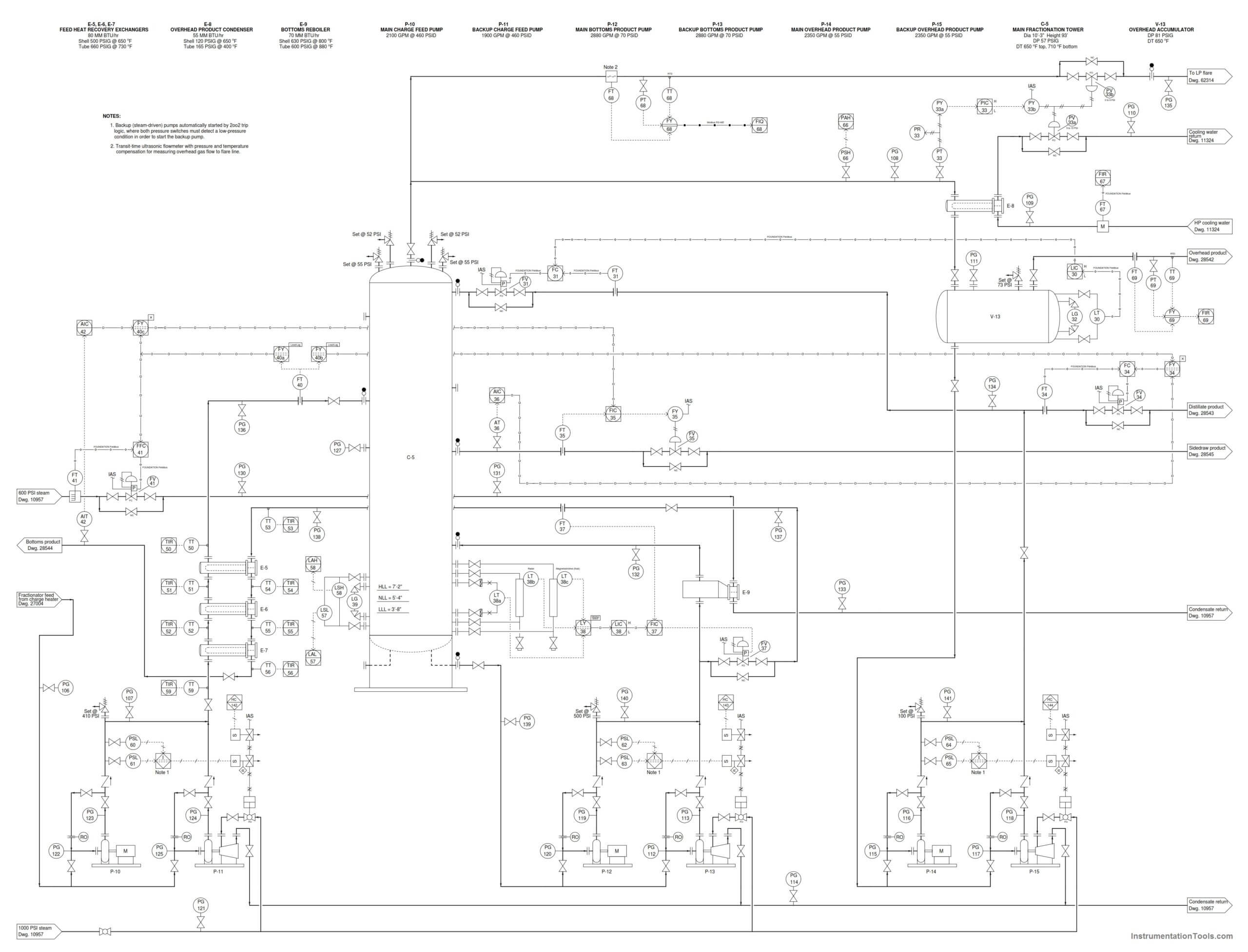
Identify the purpose of the flow ratio controller FFC-41 in this distillation process piping and instrumentation diagram (P&ID).

Flow Ratio Controller

Purpose of Flow Ratio ControllerClick on the Image to Zoom
Answer:

The purpose of FFC-41 is to control the flow of 600 PSI steam to the bottoms reboiler (heat exchanger E-9) in accordance with the feed flow rate in. The feed flow is, therefore, the “wild” flow and the steam flow is the “captive” flow.

The ratio of steam flow to feed flow is automatically adjusted by AIT-42 sensing something about the composition of the bottoms product (perhaps density, or boiling point, or some other property related to the distillation of products within the tower).

Join the Discussion! Share your answers with us through below comments section.

Read Next:

  • Architecture of Instrumentation
  • Basic of Control Valves
  • Instrument Turndown Ratio
  • Water Filter Discharge Pressure
  • How Weigh Feeder Works?
Don't Miss Our Updates
Be the first to get exclusive content straight to your email.
We promise not to spam you. You can unsubscribe at any time.
Invalid email address
You've successfully subscribed !

Continue Reading

How a Bourdon Tube Pressure Gauge might be Adjusted for Linearity?
Calculate the Transmitter Values
Signal Strength of Guided-wave Radar Level Instrument
Resistance Temperature Detector (RTD) Questions – 2
Practical Process Control System Questions & Answers – 12
Calculate 0%, 50%, and 100% Calibration Points for ΔP transmitter
Share This Article
Facebook Whatsapp Whatsapp LinkedIn Copy Link
Share
Leave a Comment

Leave a Reply Cancel reply

Your email address will not be published. Required fields are marked *

Stay Connected

128.3kFollowersLike
69.1kFollowersFollow
210kSubscribersSubscribe
38kFollowersFollow

Categories

Explore More

Process Control Loop Testing
Practical Process Control System Questions & Answers – 7
Which Instrument is Faulty? Transmitter, Recorder, or Controller
Programmable Logic Controller (PLC) Questions and Answers – 6
Vertical Tube Liquid Level Equilibrium
Determine LRV and URV settings for the Level Transmitter
LRV and URV of PT for Extreme Limits of Empty and Full
Instrument Salesperson Question

Keep Learning

Calculate Amount of Weight Indicated by the Scale

Calculate Amount of Weight Indicated by the Scale

Relay ladder diagram example

How to Draw a Schematic Diagram ?

Practical Control Systems Questions & Answers

Practical Process Control System Questions & Answers – 1

Problem on Weigh feeder

Problem on Weigh feeder

level control system

Practical Process Control System Questions & Answers – 10

Foxboro model 13 DP transmitter

Re-calibrate the Foxboro DP Pneumatic Transmitter

Simple High Level Indicator Circuit

Simple High Level Indicator Circuit

Calculate the Thermocouple’s Measurement Junction Temperature

Calculate the Thermocouple’s Measurement Junction Temperature

Learn More

Introduction of Urea Bagging machine

Introduction to Urea Bagging Machine

electrical-drives-questions-answers

Electrical Drives Questions & Answers

PLC Program for Blinking Lamp on 5 Seconds Interval

PLC Program for Blinking Lamp on 5 Seconds Interval

Hydrostatic pressure Measurement

Basics of Hydrostatic Level Measurement

Power Electronics Objective Questions

Voltage Control in Inverters Objective Questions

Cold Email Deliverability

Cold Email Deliverability – Latest Comprehensive Guide

Top 10 Facts about HART Technology

What is HART, Foundation Fieldbus & Profibus ?

PLC Conveyor Forward and Reverse Logic

Advanced PLC Conveyor Control: Forward and Reverse Rotation

Menu

  • About
  • Privacy Policy
  • Copyright

Quick Links

  • Learn PLC
  • Helping Hand
  • Part Time Job

YouTube Subscribe

Follow US
All rights reserved. Reproduction in whole or in part without written permission is prohibited.
Welcome Back!

Sign in to your account

Username or Email Address
Password

Lost your password?