Control valves are designed to throttle and not necessary to close 100%.
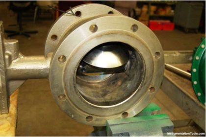
A control valve’s ability to shut off has to do with many factors as the type of valves for instance. A double seated control valve have very poor shut off capability. The guiding, seat material, actuator thrust, pressure drop, and the type of fluid can all play a part in how well a particular control valve shuts off.
Control Valves Leakage Classifications
The ANSI standard FCI 70-2: Control Valve Seat Leakage, establishes a series of six seat leakage classes for control valves and defines the test procedures.
Class I
It Is also know as dust tight and can refer to metal or resilient seated valves.
Class II
This class establishes the maximum permissible leakage generally associated with commercial double-seat control valves or balanced single-seat control valves with a piston ring seal and metal-to-metal seats.
Class III
This class establishes the maximum permissible leakage generally associated with Class II (4.2.2), but with a higher degree of seat and seal tightness.
Class IV
This class establishes the maximum permissible leakage generally associated with commercial unbalanced single-seat control valves and balanced single-seat control valves with extra tight piston rings or other sealing means and metal-to-metal seats.
Class V
This class is usually specified for critical applications where the control valve may be required to be closed, without a blocking valve, for long periods of time with high differential pressure across the seating surfaces.
It requires special manufacturing, assembly and testing techniques. This class is generally associated with metal seat, unbalanced single-seat control valves or balanced single-seat designs with exceptional seat and seal tightness.
CLASS VI
This class establishes the maximum permissible seat leakage generally associated with resilient seating control valves either unbalanced or balanced single-seat with “O” rings or similar gap less seals.
Types of Leakage
There are two types of leakage from a valve, namely; fugitive emissions from the valve to atmosphere, and leakage through the valve but contained within the piping system.
Fugitive emissions can both be detrimental to the environment and a potential safety hazard. Valves are considered to be the major contributors to fugitive emission losses.
Leakage through the valve can also be a safety hazard, and can be detrimental to the process.
Reasons of Valves leak
Common causes of leakage through the valve include:
- Valve is not fully closed. This can be due to various reasons, including;
- Valve seat is prevented from closing fully due to dirt, rust, or line debris
- Insufficient actuator travel
- The seat is damaged, e.g. scored
- The seal is damaged
Common causes of leakage to atmosphere:
- Gasket between valve-body and valve-bonnet is damaged
- Stem Pakking is worn, loose or damaged
Both of them can have several causes
Details of Seat Leakage Classifications
There are actually six different seat leakage classifications as defined by ANSI/FCI 70-2 1976(R1982).
The most common used are
- CLASS IV
- CLASS VI
CLASS IV is also known as metal to metal. It is the kind of leakage rate you can expect from a valve with a metal plug and metal seat.
CLASS VI is known as a soft seat classification. Soft Seat Valves are those where either the plug or seat or both are made from some kind of composition material such as Teflon or similar.
Valve Leakage Classifications
The different valve leakage classifications are as follows :
Class I – Valve Leakage Classifications
Identical to Class II, III, and IV in construction and design intent, but no actual shop test is made. Class I is also known as dust tight and can refer to metal or resilient seated valves.
Class II – Valve Leakage Classifications
Intended for double port or balanced singe port valves with a metal piston ring seal and metal to metal seats.
- 0.5% leakage of full open valve capacity.
- Service dP or 50 psid (3.4 bar differential), whichever is lower at 50 to 125 deg F.
- Test medium air at 45 to 60 psig is the test fluid.
Typical constructions:
- Balanced, single port, single graphite piston ring, metal seat, low seat load
- Balanced, double port, metal seats, high seat load
Class III – Valve Leakage Classifications
Intended for the same types of valves as in Class II.
- 0.1% leakage of full open valve capacity.
- Service dP or 50 psid (3.4 bar differential), whichever is lower at 50 to 125oF.
- Test medium air at 45 to 60 psig is the test fluid.
Typical constructions:
- Balanced, double port, soft seats, low seat load
- Balanced, single port, single graphite piston ring, lapped metal seats, medium seat load
Class IV – Valve Leakage Classifications
Intended for single port and balanced single port valves with extra tight piston seals and metal to-metal seats.
- 0.01% leakage of full open valve capacity.
- Service dP or 50 psid (3.4 bar differential), whichever is lower at 50 to 125oF.
- Test medium air at 45 to 60 psig is the test fluid.
Typical constructions:
- Balanced, single port, Teflon piston ring, lapped metal seats, medium seat load
- Balanced, single port, multiple graphite piston rings, lapped metal seats
- Unbalanced, single port, lapped metal seats, medium seat load
- Class IV is also known as metal to metal
Class V – Valve Leakage Classifications
Intended for the same types of valves as Class IV.
- The test fluid is water at 100 psig or operating pressure.
- Leakage allowed is limited to 5 x 10 ml per minute per inch of orifice diameter per psi differential.
- Service dP at 50 to 125 deg F.
Typical constructions:
- Unbalanced, single port, lapped metal seats, high seat load
- Balanced, single port, Teflon piston rings, soft seats, low seat load
- Unbalanced, single port, soft metal seats, high seat load
Class VI – Valve Leakage Classifications
Class VI is known as a soft seat classification. Soft Seat Valves are those where the seat or shut-off disc or both are made from some kind of resilient material such as Teflon. Intended for resilient seating valves.
- The test fluid is air or nitrogen.
- Pressure is the lesser of 50 psig or operating pressure.
- The leakage limit depends on valve size and ranges from 0.15 to 6.75 ml per minute for valve sizes 1 through 8 inches.
Typical constructions:
- Unbalanced, single port, soft seats, low load

Control Valve Seat Leakage Classifications