The most important reason why people prefer installing Thermowell on Elbow is that it saves from Wake frequency calculation (WFC).
Hence It is of paramount importance to effectively install thermowell to achieve its desired purpose.
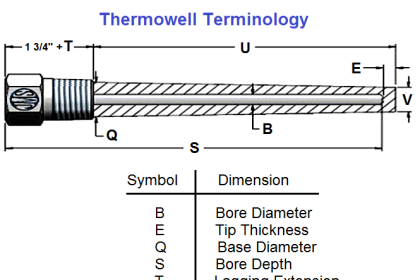
Thermowell Installation

There are 4 main parameters to check
- The Direction of flow in a pipe (Tip must face the direction of flow)
- Acceptance from other disciplines especially process department
- Clearance space to remove the Temperature assembly outside
- In case of Test well Ease of Accessibility
Why check the direction of flow?
The Vortices are formed when a body is placed perpendicular to flow.
Now when we install the Thermowell in Elbow our aim is to achieve as little contact of thermowell “perpendicular” to flow
Case one tip is facing downstream of the elbow
(Apologies:-due to lack of time had to draw them by hand)

It is clearly observed that the perpendicular area exposed to flow is more
Now compare that to tip facing Upstream of Elbow

We see that when the tip is facing the upstream the area “perpendicular” to flow is very minimal
Hence very minimum von karman vortex and thus less stress on thermowell
Thermowells mounted in an elbow with the tip pointing upstream, as shown are often preferable to a mounting with the tip pointing downstream…… Reference ASME PTC 19.3 TW-2016 Page no 28.
NOTE: Major Petrochem companies of the world in their design bases mention that WFC should be in compliance with ASME PTC 19.3
Approval from other disciplines?
In the Below, picture assume our thermowell is at this location
 Now we might feel we can mount it on the elbow but wait for in-between there is another line joining our line.
So the process might want to measure the temperature of liquid before mixing and thus even though other considerations are fulfilled we still cannot go for Elbow installations.
Clearance space for Thermowell?
This is simple to understand If you want to remove thermowell outside or install.
The has to be some clearance space to physically remove the Temperature assembly.
It should be around 610 mm (24 inches)
OR
The total length of thermowell + 76mm (3 Inches)….Whichever is greater
(Reference API 551 Page no 25 )
In case of Test well Ease of Accessibility
It is recommended that Test wells must be very easily accessible and hence if Elbow is at a great height then it must be discussed and the amicable solution is required.
In some cases, I have notice clients not accepting Elbow installation as they would want the test well to be readily accessible.
Thanks for reading !!
I hope it’s been valuable to you.
A question for you:-
What do you think if there is Perpendicular installation or “Angular” Thermowell installation which one would have lower stress due to von karman vortex and why?
PS: This is as per the best of my current understanding.
Author : Asad Shaikh
Profile : Linkedin


Another technique to reduce von Karma vortices and its resultant effect on temperature measurement is to carry out installation of thermowells at angles less than 90 degrees. This is recommended for process lines where measurements are required at non-elbow points.