Inst ToolsInst ToolsInst Tools
  • Ask
  • Courses
  • Videos
  • Q & A
    • Interview
      • Instrumentation
      • Electronics
      • Electrical
      • Practical Questions
    • MCQ
      • Instrumentation MCQ
      • Electrical MCQ
      • Electronics MCQ
      • Control Systems MCQ
      • Analog Electronics MCQ
      • Digital Electronics MCQ
      • Power Electronics MCQ
      • Microprocessor MCQ
      • Multiple Choice Questions
  • EE
    • Electronics
      • Electronics Q & A
      • Electronic Basics
      • Electronic Devices & Circuits
      • Electronics Animation
      • Digital Electronics
    • Electrical
      • Electrical Basics
      • Electrical Q & A
      • Power Electronics
      • Electrical Machines
      • Electrical Animation
      • Power Systems
      • Switchgear & Protection
      • Transmission & Distribution
  • Measure
    • Control Valves
    • Calibration
    • Temperature
    • Pressure
    • Flow
    • Level
    • Analyzers
    • Switches
    • Vibration
    • Solenoid Valve
  • Control
    • PLC Tutorials
    • Control Systems
    • Safety Instrumented System (SIS)
    • Communication
    • Fire & Gas System
  • More
    • Design
    • Tools
    • Animation
    • Basics
    • Formulas
    • Standards
    • TextBooks
    • Common
    • Software
    • Excel Tools
    • Erection & Commissioning
    • Process Fundamentals
    • Videos
    • Books
Search
All rights reserved. Reproduction in whole or in part without written permission is prohibited.
Reading: Ladder Logic for Stair-Case wiring using Toggle Switches
Share
Notification Show More
Font ResizerAa
Inst ToolsInst Tools
Font ResizerAa
  • Courses
  • PLC Tutorials
  • Control Systems
Search
  • Ask
  • Courses
  • Videos
  • Q & A
    • Interview
    • MCQ
  • EE
    • Electronics
    • Electrical
  • Measure
    • Control Valves
    • Calibration
    • Temperature
    • Pressure
    • Flow
    • Level
    • Analyzers
    • Switches
    • Vibration
    • Solenoid Valve
  • Control
    • PLC Tutorials
    • Control Systems
    • Safety Instrumented System (SIS)
    • Communication
    • Fire & Gas System
  • More
    • Design
    • Tools
    • Animation
    • Basics
    • Formulas
    • Standards
    • TextBooks
    • Common
    • Software
    • Excel Tools
    • Erection & Commissioning
    • Process Fundamentals
    • Videos
    • Books
Follow US
All rights reserved. Reproduction in whole or in part without written permission is prohibited.
Inst Tools > Blog > PLC Tutorials > Ladder Logic for Stair-Case wiring using Toggle Switches

Ladder Logic for Stair-Case wiring using Toggle Switches

Last updated: March 4, 2021 3:22 pm
Editorial Staff
PLC Tutorials
No Comments
Share
2 Min Read
SHARE

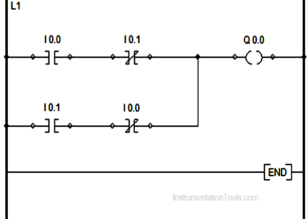
Design Ladder Logic for Stair-Case wiring using two Toggle Switches in programmable logic controllers (PLC).

  • I0.0 & I0.1 : Input toggle switches.
  • Q0.0 : Output signaling device(bulb, motor etc.)

Ladder Logic for Stair-Case wiring

This ladder logic of stair-case wiring works on the X-OR logic i.e, Y is (A.B^) + (A^. B)

Suppose initially only I0.0 is pressed and I0.1 remains open physically as shown then the upper branch of rung 1 goes TRUE  and Q0.0 gets energized.
Ladder Logic for Stair-Case wiring using Toggle Switches

Now , if I0.0 is also pressed then it will make its interlock N-C contact I0.1 to go open and as a result Q0.0 de-energizes .

Again, if switch I0.0 is pressed it will also make its interlock contact I0.0 in parallel branch to go again N-C , which in turn makes the parallel branch logic true and Q0.0 again energizes but if the I0.1  input is also pressed again the logic goes FALSE and Q0.0 again de-energizes. This is the basic concept of an X-OR logic gate.

If you liked this article, then please subscribe to our YouTube Channel for PLC and SCADA video tutorials.

You can also follow us on Facebook and Twitter to receive daily updates.

Read Next:

Motor Start Stop Logic using PLC
PLC Program for Blinking Lamp

Multi Way Switches using PLC

How to use PLC Sub Routines

Down Counter PLC Logics

Don't Miss Our Updates
Be the first to get exclusive content straight to your email.
We promise not to spam you. You can unsubscribe at any time.
Invalid email address
You've successfully subscribed !
What is a Retro-Reflective Sensor? – Principle, Applications
PLC Program for Traffic Light Sequence using Functional Blocks
PLC Output Types
PLC Analog I/O Potential Problems – Troubleshooting & Issues
UPS Selection Factors for a Control System
Share This Article
Facebook Whatsapp Whatsapp LinkedIn Copy Link
Share
Leave a Comment

Leave a Reply Cancel reply

Your email address will not be published. Required fields are marked *

Stay Connected

128.3kFollowersLike
69.1kFollowersFollow
208kSubscribersSubscribe
38kFollowersFollow

Categories

Recent Comments

  • Kamli on Top Free PLC Software
  • Guifty Shimica on Top Non-PLC Certification Courses for Automation Professionals
  • Guifty Shimica on Top Non-PLC Certification Courses for Automation Professionals
  • MIHARITSOA Aina Sitraka on Top Non-PLC Certification Courses for Automation Professionals

Related Articles

Scaling in PLC

PLC Ladder Logic for Sensor Scaling with Offset

PLC Program for Automatic Bottle Rejection System

PLC Program for Automatic Bottle Rejection System

PLC Example on Switch Program with Timers

PLC Example on Switch Program with Timers

Compile Project in Tia Portal

Communication between Wincc and Tia Portal

PLC Program for Water Level Control

PLC Program for Water Level Control Logic

PLC Sequential Operation Example Program

PLC Sequential Operation Example Program

How to Train Your Maintenance Team for Industrial Automation Systems

How to Train Your Maintenance Team for Industrial Automation Systems?

Structured Text in PLC: Parking Information Systems

Structured Text in PLC: Parking Information Systems

More Articles

Selecting the Best Inductive or Capacitive Sensor

Selecting the Best Inductive or Capacitive Sensor

Basic Transistor Amplifier Circuit Principle

Basic Transistor Amplifier Circuit Principle

Why are Impulse Lines often Installed in a Sloping Manner (Angle)

Why are Impulse Lines often Installed in a Sloping Manner?

Phase Failure Relay

Why is Phase Failure Relay Required in LV Panels?

Instrumentation Engineering Quiz

Instrumentation Engineering Quiz – Set 2

Top Most Popular CNC Software Programs

Top Most Popular CNC Software Programs – A Comprehensive List

On Off Valve Root Cause Analysis

Root Cause Analysis for FRP Line Damaged due to On-Off Valve

Voltage Control Methods at Distribution System

Factors affect Voltage Level Selection in Service System

Follow US
All rights reserved. Reproduction in whole or in part without written permission is prohibited.
Welcome Back!

Sign in to your account

Username or Email Address
Password

Lost your password?