Inst ToolsInst ToolsInst Tools
  • Courses
  • Automation
    • PLC
    • Control System
    • Safety System
    • Communication
    • Fire & Gas System
  • Instrumentation
    • Design
    • Pressure
    • Temperature
    • Flow
    • Level
    • Vibration
    • Analyzer
    • Control Valve
    • Switch
    • Calibration
    • Erection & Commissioning
  • Interview
    • Instrumentation
    • Electrical
    • Electronics
    • Practical
  • Q&A
    • Instrumentation
    • Control System
    • Electrical
    • Electronics
    • Analog Electronics
    • Digital Electronics
    • Power Electronics
    • Microprocessor
  • Request
Search
  • Books
  • Software
  • Projects
  • Process
  • Tools
  • Basics
  • Formula
  • Power Plant
  • Root Cause Analysis
  • Electrical Basics
  • Animation
  • Standards
  • 4-20 mA Course
  • Siemens PLC Course
Reading: PLC Automatic Pedal Switch for Speed Control
Share
Font ResizerAa
Inst ToolsInst Tools
Font ResizerAa
  • Courses
  • Design
  • PLC
  • Interview
  • Control System
Search
  • Courses
  • Automation
    • PLC
    • Control System
    • Safety System
    • Communication
    • Fire & Gas System
  • Instrumentation
    • Design
    • Pressure
    • Temperature
    • Flow
    • Level
    • Vibration
    • Analyzer
    • Control Valve
    • Switch
    • Calibration
    • Erection & Commissioning
  • Interview
    • Instrumentation
    • Electrical
    • Electronics
    • Practical
  • Q&A
    • Instrumentation
    • Control System
    • Electrical
    • Electronics
    • Analog Electronics
    • Digital Electronics
    • Power Electronics
    • Microprocessor
  • Request
Follow US
All rights reserved. Reproduction in whole or in part without written permission is prohibited.
Inst Tools > Blog > PLC Tutorials > PLC Automatic Pedal Switch for Speed Control

PLC Automatic Pedal Switch for Speed Control

Last updated: March 4, 2021 3:51 pm
Editorial Staff
PLC Tutorials
No Comments
Share
3 Min Read
SHARE

We need to use pedal switch control logic at machine work shop for speed control of motor. Write the PLC program for this application using ladder diagram.

Contents
Pedal Switch for Speed ControlPLC SolutionList of Inputs/OutputsPLC Logic Automatic pedal switch for Speed ControlLadder Logic Description

Pedal Switch for Speed Control

PLC Automatic Pedal Switch for Speed Control

PLC Solution

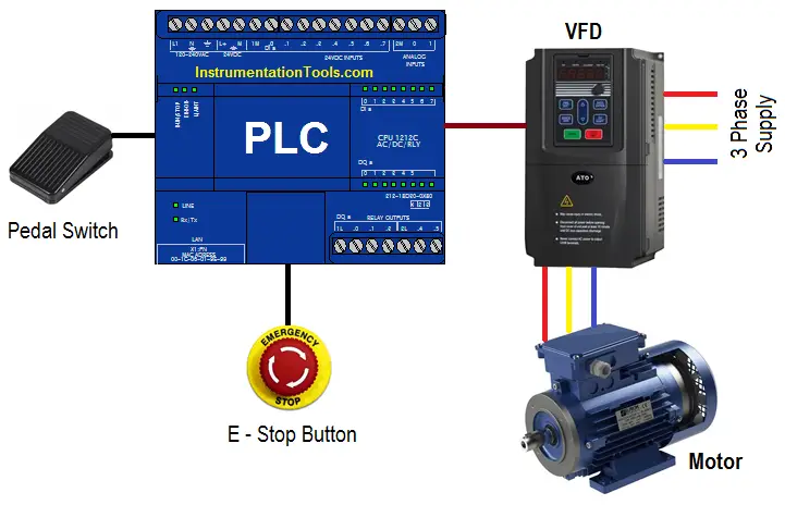
Here we want to operate machine in two different speeds. For this control, we are using pedal switch so we can control the speed of motor.

For normal operation we need to operate machine in speed 1 condition. And for higher operation we need to operate machine in speed 2.

Here we have considered two different speeds of motor. so, by pressing pedal switch first time motor can be started at speed 1. When user will press pedal switch again motor will run at speed 2.

Motor can be stopped by pressing E stop button.

List of Inputs/Outputs

List of Inputs

  • I1 : Pedal switch
  • I2 : E stop button

List of Outputs

  • Q1 : Speed 1
  • Q2 : Speed 2

PLC Logic Automatic pedal switch for Speed Control
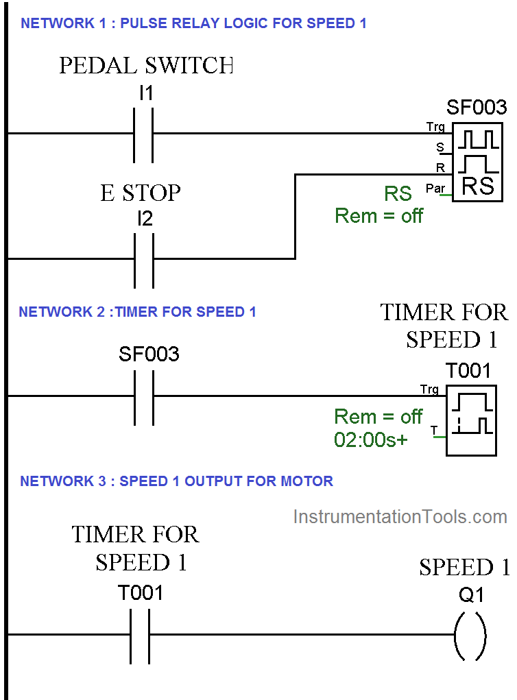
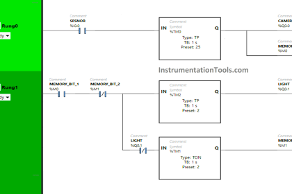
PLC Pedal Switch Logic for Speed Control
PLC Switch Ladder Diagram

Ladder Logic Description

Network 1 :-

In this network, we have used pulse relay instruction for speed 1 output.

Network 2 :-

When pedal switch is triggered first time, it will operate on delay timer.

Network 3 :-

After some 2s delay motor will run at first speed.

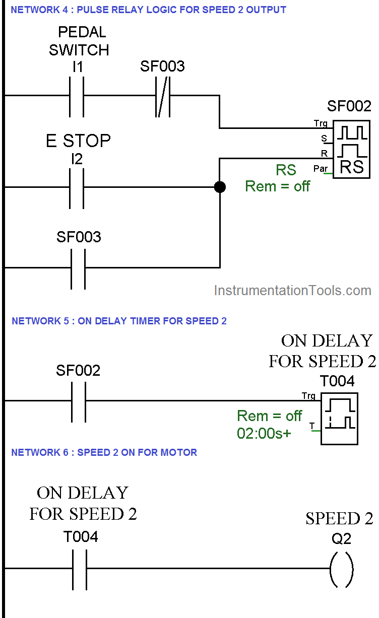
Network 4 :-

In this network we have used another pulse relay instruction for the speed 2 output.

Network 5 :-

When pedal switch is triggered second time, it will operate on delay timer for the speed 2.

Network 6 :-

When timer is completed, motor will run at speed 2.

Note:- Above application may be different from actual application. This example is only for explanation purpose only. We can implement this logic in other PLC also. This is the simple automatic pedal switch for speed selection using PLC, we can use this concept in other examples also.

All parameters and graphical representations considered in this example are for explanation purpose only, parameters or representation may be different in actual applications. Also all interlocks are not considered in the application.

Author : Bhavesh

If you liked this article, then please subscribe to our YouTube Channel for PLC and SCADA video tutorials.

You can also follow us on Facebook and Twitter to receive daily updates.

Read Next:

Variable Frequency Drive (VFD)
Types of AC and DC Motors

Stepper Motor Principle

Electrical Drives Questions

PLC Pump Control Video

Don't Miss Our Updates
Be the first to get exclusive content straight to your email.
We promise not to spam you. You can unsubscribe at any time.
Invalid email address
You've successfully subscribed !

Continue Reading

Count the Number of Cartons in a Storage Area PLC Logic
#16 PLC Best Practices – Create Trend for Cycle Time on HMI
Instrumentation and Control Project Packages – Detail Engineering
Advanced PLC Conveyor Control: Forward and Reverse Rotation
How to Design an Effective HMI? – Human Machine Interface
How CPU Execute Program in Siemens PLC?
Share This Article
Facebook Whatsapp Whatsapp LinkedIn Copy Link
Share
Leave a Comment

Leave a Reply Cancel reply

Your email address will not be published. Required fields are marked *

Stay Connected

128.3kFollowersLike
69.1kFollowersFollow
210kSubscribersSubscribe
38kFollowersFollow

Categories

Explore More

What are Functions in PLC Programming? (FCs)
Loop Check of 4-20mA or HART Transmitters
How to Control VFD with PLC using Ladder Logic
Automated Test Bench – Complex PLC Programming Examples
Free Schneider PLC Training – Automation Course
PLC Programming for Weight-Based Packaging
Developing PLC Logic for Water Pumping and Chemical Addition
Compare Modbus, Fieldbus, and Profibus

Keep Learning

Advanced Ladder Logic PLC Example

Automatic Sanitizer – Complex Ladder Logic PLC Examples

PLC Program for Tank Heating Control using Heater

PLC Programming for Tank Heating Control using Heater

PLC Retrofitting Project

What is a PLC Retrofitting Project? – Importance, Procedure

Micro PLC

Micro PLC Hardware Configuration

CPU Communication Ports in Siemens PLC

Types of CPU Communication Ports in Siemens PLC

Open PLC Software

Open Source PLC and SCADA Software

Split Range Control Block Diagram

Split Range Control Application using PLC Ladder Logic

PLC Program using START & STOP Buttons

PLC Program using START and STOP Buttons

Learn More

Turbine Flowmeter Parts

What is a Turbine Flow Meter?

Fire and Gas System Interview Questions & Answers

Fire and Gas System Interview Questions & Answers

Identify Instruments in Piping and instrumentation Diagram

Identify Instruments in Piping and instrumentation Diagram

STL Programming - SET, RESET, ASSIGN

STL Programming – SET, RESET, ASSIGN

Advantages and Disadvantages of Network Topology

Advantages and Disadvantages of Per Unit System

Set the S5 timer value by a memory word

Set the S5 Timer Value by a Memory Word

Digital Electronics Multiple Choice Questions

Multivibrators Objective Questions

Thermocouple Material Characteristics

Thermocouple Construction

Menu

  • About
  • Privacy Policy
  • Copyright

Quick Links

  • Learn PLC
  • Helping Hand
  • Part Time Job

YouTube Subscribe

Follow US
All rights reserved. Reproduction in whole or in part without written permission is prohibited.
Welcome Back!

Sign in to your account

Username or Email Address
Password

Lost your password?