Inst ToolsInst ToolsInst Tools
  • Ask
  • Courses
  • Videos
  • Q & A
    • Interview
      • Instrumentation
      • Electronics
      • Electrical
      • Practical Questions
    • MCQ
      • Instrumentation MCQ
      • Electrical MCQ
      • Electronics MCQ
      • Control Systems MCQ
      • Analog Electronics MCQ
      • Digital Electronics MCQ
      • Power Electronics MCQ
      • Microprocessor MCQ
      • Multiple Choice Questions
  • EE
    • Electronics
      • Electronics Q & A
      • Electronic Basics
      • Electronic Devices & Circuits
      • Electronics Animation
      • Digital Electronics
    • Electrical
      • Electrical Basics
      • Electrical Q & A
      • Power Electronics
      • Electrical Machines
      • Electrical Animation
      • Power Systems
      • Switchgear & Protection
      • Transmission & Distribution
  • Measure
    • Control Valves
    • Calibration
    • Temperature
    • Pressure
    • Flow
    • Level
    • Analyzers
    • Switches
    • Vibration
    • Solenoid Valve
  • Control
    • PLC Tutorials
    • Control Systems
    • Safety Instrumented System (SIS)
    • Communication
    • Fire & Gas System
  • More
    • Design
    • Tools
    • Animation
    • Basics
    • Formulas
    • Standards
    • TextBooks
    • Common
    • Software
    • Excel Tools
    • Erection & Commissioning
    • Process Fundamentals
    • Videos
    • Books
Search
All rights reserved. Reproduction in whole or in part without written permission is prohibited.
Reading: How to do Continuity Testing using Multimeter
Share
Notification Show More
Font ResizerAa
Inst ToolsInst Tools
Font ResizerAa
  • Courses
  • PLC Tutorials
  • Control Systems
Search
  • Ask
  • Courses
  • Videos
  • Q & A
    • Interview
    • MCQ
  • EE
    • Electronics
    • Electrical
  • Measure
    • Control Valves
    • Calibration
    • Temperature
    • Pressure
    • Flow
    • Level
    • Analyzers
    • Switches
    • Vibration
    • Solenoid Valve
  • Control
    • PLC Tutorials
    • Control Systems
    • Safety Instrumented System (SIS)
    • Communication
    • Fire & Gas System
  • More
    • Design
    • Tools
    • Animation
    • Basics
    • Formulas
    • Standards
    • TextBooks
    • Common
    • Software
    • Excel Tools
    • Erection & Commissioning
    • Process Fundamentals
    • Videos
    • Books
Follow US
All rights reserved. Reproduction in whole or in part without written permission is prohibited.
Inst Tools > Blog > Electronic Basics > How to do Continuity Testing using Multimeter

How to do Continuity Testing using Multimeter

Last updated: April 27, 2017 4:21 am
Editorial Staff
Electronic Basics
No Comments
Share
3 Min Read
SHARE

Continuity Testing using MultimeterContinuity Testing using Multimeter

  1. Turn the dial to Continuity Test mode ( Continuity Mode ). It will likely share a spot on the dial with one or more functions, usually resistance (Ω). With the test probes separated, the multimeter’s display may show OL and Ω.
  2. If required, press the continuity button.
  3. First insert the black test lead into the COM jack.
  4. Then insert the red lead into the V Ω jack. When finished, remove the leads in reverse order: red first, then black.
  5. With the circuit de-energized, connect the test leads across the component being tested. The position of the test leads is arbitrary. Note that the component may need to be isolated from other components in the circuit.
  6. The digital multimeter (DMM) beeps if a complete path (continuity) is detected. If the circuit is open (the switch is in the OFF position), the DMM will not beep.
  7. When finished, turn the multimeter OFF to preserve battery life.

Continuity testing overview

  • Continuity is the presence of a complete path for current flow. A circuit is complete when its switch is closed.
  • A digital multimeter’s Continuity Test mode can be used to test switches, fuses, electrical connections, conductors and other components. A good fuse, for example, should have continuity.
  • A DMM emits an audible response (a beep) when it detects a complete path.
  • The beep, an audible indicator, permits technicians to focus on testing procedures without looking at the multimeter display.
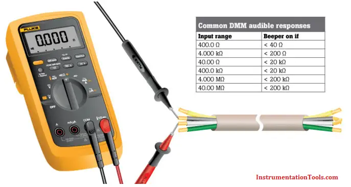
  • When testing for continuity, a multimeter beeps based on the resistance of the component being tested. That resistance is determined by the range setting of the multimeter. Examples:
    • If the range is set to 400.0 Ω, a multimeter typically beeps if the component has a resistance of 40 Ω or less.
    • If the range is set 4.000 kΩ, a multimeter typically beeps if the component has a resistance of 200 Ω or less.
  • The lowest range setting should be used when testing circuit components that should have low-resistance value such as electrical connections or switch contacts.

Continuity Mode in Multimeter

Source : Fluke

Also Read: Measure Frequency using Multimeter

Don't Miss Our Updates
Be the first to get exclusive content straight to your email.
We promise not to spam you. You can unsubscribe at any time.
Invalid email address
You've successfully subscribed !
Factors Affecting Inductance
Definition of Accuracy, Precision, Resolution, Range
Difference Between LED and LCD
Difference Between LDR and Photodiode
How to Use SMD Components in Electronic Circuits?
Share This Article
Facebook Whatsapp Whatsapp LinkedIn Copy Link
Share
Leave a Comment

Leave a Reply Cancel reply

Your email address will not be published. Required fields are marked *

Stay Connected

128.3kFollowersLike
69.1kFollowersFollow
208kSubscribersSubscribe
38kFollowersFollow

Categories

Recent Comments

  • Guifty Shimica on Top Non-PLC Certification Courses for Automation Professionals
  • Guifty Shimica on Top Non-PLC Certification Courses for Automation Professionals
  • MIHARITSOA Aina Sitraka on Top Non-PLC Certification Courses for Automation Professionals
  • Vaishnavi on Free Instrumentation Course for Trainee Engineers

Related Articles

Clamp meters

Clamp Meters Working Principle

How to Test a Transistor using Multimeter

How to Test a Transistor using Multimeter

Testing a defective transistor

Testing a Transistor with a Digital Multimeter

What is PCB Corrosion - Electronic Boards Corrosion Prevention

What is PCB Corrosion? Electronic Boards Corrosion Prevention

Switched Mode Power Supply (SMPS)

How does SMPS Works? – Switched Mode Power Supply

What is a Fuse

What is a Fuse ?

How to Test a Battery using Multimeter

How to Test a Battery using a Multimeter?

What is Oscilloscope

What is Cathode Ray oscilloscope ?

More Articles

Instrument Skid

What is an Instrument Skid? – Example of Metering Skid

Closed tank DP Level Transmitter with wet leg elevation zero remote mount Calibration

Closed tank DP Level Transmitter with wet leg elevation zero remote mount Calibration

Top Electrical Engineering Interview Questions for Freshers

Latest Electrical Motors Questions and Answers

Safety Relief Valve Material Selection

Allen Bradley PLC ControlLogix Hardware

Allen Bradley PLC ControlLogix Hardware

pressure switches relay circuit

Determine the functions of Pressure Switches ?

PLC Program to Control Motor Speed using VFD Drive

Motor Speed Control using VFD and PLC Programming

Synchronous Motor Is Not Self Starting?

Follow US
All rights reserved. Reproduction in whole or in part without written permission is prohibited.
Welcome Back!

Sign in to your account

Username or Email Address
Password

Lost your password?