Inst ToolsInst ToolsInst Tools
  • Ask
  • Courses
  • Videos
  • Q & A
    • Interview
      • Instrumentation
      • Electronics
      • Electrical
      • Practical Questions
    • MCQ
      • Instrumentation MCQ
      • Electrical MCQ
      • Electronics MCQ
      • Control Systems MCQ
      • Analog Electronics MCQ
      • Digital Electronics MCQ
      • Power Electronics MCQ
      • Microprocessor MCQ
      • Multiple Choice Questions
  • EE
    • Electronics
      • Electronics Q & A
      • Electronic Basics
      • Electronic Devices & Circuits
      • Electronics Animation
      • Digital Electronics
    • Electrical
      • Electrical Basics
      • Electrical Q & A
      • Power Electronics
      • Electrical Machines
      • Electrical Animation
      • Power Systems
      • Switchgear & Protection
      • Transmission & Distribution
  • Measure
    • Control Valves
    • Calibration
    • Temperature
    • Pressure
    • Flow
    • Level
    • Analyzers
    • Switches
    • Vibration
    • Solenoid Valve
  • Control
    • PLC Tutorials
    • Control Systems
    • Safety Instrumented System (SIS)
    • Communication
    • Fire & Gas System
  • More
    • Design
    • Tools
    • Animation
    • Basics
    • Formulas
    • Standards
    • TextBooks
    • Common
    • Software
    • Excel Tools
    • Erection & Commissioning
    • Process Fundamentals
    • Videos
    • Books
Search
All rights reserved. Reproduction in whole or in part without written permission is prohibited.
Reading: 7 OSI Layers of Communication
Share
Notification Show More
Font ResizerAa
Inst ToolsInst Tools
Font ResizerAa
  • Courses
  • PLC Tutorials
  • Control Systems
Search
  • Ask
  • Courses
  • Videos
  • Q & A
    • Interview
    • MCQ
  • EE
    • Electronics
    • Electrical
  • Measure
    • Control Valves
    • Calibration
    • Temperature
    • Pressure
    • Flow
    • Level
    • Analyzers
    • Switches
    • Vibration
    • Solenoid Valve
  • Control
    • PLC Tutorials
    • Control Systems
    • Safety Instrumented System (SIS)
    • Communication
    • Fire & Gas System
  • More
    • Design
    • Tools
    • Animation
    • Basics
    • Formulas
    • Standards
    • TextBooks
    • Common
    • Software
    • Excel Tools
    • Erection & Commissioning
    • Process Fundamentals
    • Videos
    • Books
Follow US
All rights reserved. Reproduction in whole or in part without written permission is prohibited.
Inst Tools > Blog > Communication > 7 OSI Layers of Communication

7 OSI Layers of Communication

Last updated: June 8, 2018 2:50 pm
Editorial Staff
Communication
2 Comments
Share
3 Min Read
SHARE

ISO/OSI Model

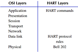
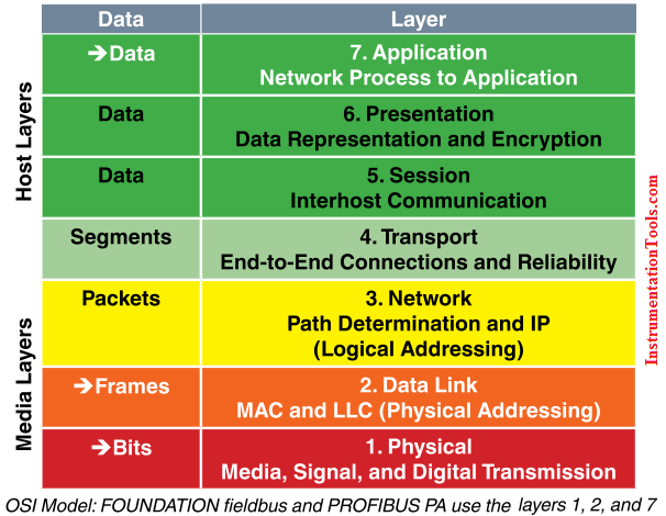
The International Standards Organization (ISO) has determined a general architecture of network specifications in their DIS 7498 model (applicable to most any digital network). These network specifications were developed as part of the Open  Systems Interconnection (OSI) initiative to define the layering of communications in network protocol design. The OSI protocol stack  is split into seven layers for modularity. All of the software layers work together, building and distributing the communications. Not all network protocols use  every layer.

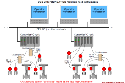
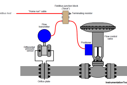
Digital fieldbus systems (FOUNDATION fieldbus and PROFIBUS PA) use  three  of the seven layers: 1, 2, and 7. This is because physical and logical layers are the same and there  is no direct communication from one node  to another across different segments.

7 OSI Layers of Communications

The Layers in Detail

■  Level 1 – Physical Layer: Defines the electrical  and physical  specifications for devices. In particular,  the physical  layer defines the relationship between a device and a physical  medium. This relationship includes the layout of pins, voltages, and cable  specifications.

■  Level 2 – Data Link Layer: Is the protocol layer that transfers data  between adjacent network nodes in a wide area network or between nodes on the same segment. The Data Link Layer provides the functional and procedural means to transfer  data  between network entities  and provides the means for error detection and correcting events that occur in the physical  layer.

■  Level 3 – Network Layer: Establishes procedures for the encapsulation of data into packets for transmission and reception.

■  Level 4 – Transport Layer: Defines how complete data files are handled over a network.

■  Level 5 – Session Layer: Organizes data  transfer  in terms of the start and end of a specific transmission.

■ Level 6 – Presentation Layer: Defines the character sets, terminal control, and graphics commands so that abstract data can be readily encoded and decoded between communicating devices.

■  Level 7 – Application Layer: Refers to standards for generating and/or  interpreting  communicated data  in its final form. In other words, the actual  software programs used to communicate data.

Also Read: HART vs Foundation Fieldbus
Don't Miss Our Updates
Be the first to get exclusive content straight to your email.
We promise not to spam you. You can unsubscribe at any time.
Invalid email address
You've successfully subscribed !
What is Auto-negotiation in Network?
WirelessHART
Layer-2 and Layer-3 Network Switches
Ethernet Communication Interview Questions & Answers
What is HART Protocol ?
Share This Article
Facebook Whatsapp Whatsapp LinkedIn Copy Link
Share
2 Comments
  • Paul says:
    May 22, 2017 at 1:58 am

    Aside from the issues of the physical network (signal types and voltage levels, connector pinouts, cabling, topology, etc.), there needs to be a standardized way in which communication is arbitrated between multiple nodes in a network, even if its as simple as a two-node, point-to-point system. When a node “talks” on the network, it is generating a signal on the network wiring, be it high and low DC voltage levels, some kind of modulated AC carrier wave signal, or even pulses of light in a fiber. Nodes that “listen” are simply measuring that applied signal on the network (from the transmitting node) and passively monitoring it. If two or more nodes “talk” at the same time, however, their output signals may clash (imagine two logic gates trying to apply opposite signal voltages to a single line on a bus!), corrupting the transmitted data.

    The standardized method by which nodes are allowed to transmit to the bus or network wiring is called a protocol. There are many different protocols for arbitrating the use of a common network between multiple nodes, and I’ll cover just a few here. However, its good to be aware of these few, and to understand why some work better for some purposes than others. Usually, a specific protocol is associated with a standardized type of network. This is merely another “layer” to the set of standards which are specified under the titles of various networks.

    The International Standards Organization (ISO) has specified a general architecture of network specifications in their DIS7498 model (applicable to most any digital network). Consisting of seven “layers,” this outline attempts to categorize all levels of abstraction necessary to communicate digital data.

    Level 1: Physical Specifies electrical and mechanical details of communication: wire type, connector design, signal types and levels.
    Level 2: Data link Defines formats of messages, how data is to be addressed, and error detection/correction techniques.
    Level 3: Network Establishes procedures for encapsulation of data into “packets” for transmission and reception.
    Level 4: Transport Among other things, the transport layer defines how complete data files are to be handled over a network.
    Level 5: Session Organizes data transfer in terms of beginning and end of a specific transmission. Analogous to job control on a multitasking computer operating system.
    Level 6: Presentation Includes definitions for character sets, terminal control, and graphics commands so that abstract data can be readily encoded and decoded between communicating devices.
    Level 7: Application The end-user standards for generating and/or interpreting communicated data in its final form. In other words, the actual computer programs using the communicated data.

    Reply
  • Syed Warsi says:
    July 11, 2022 at 10:38 pm

    Vert well defined at the summary level. Excellent information…

    Reply

Leave a Reply Cancel reply

Your email address will not be published. Required fields are marked *

Stay Connected

128.3kFollowersLike
69.1kFollowersFollow
208kSubscribersSubscribe
38kFollowersFollow

Categories

Recent Comments

  • Kamli on Top Free PLC Software
  • Guifty Shimica on Top Non-PLC Certification Courses for Automation Professionals
  • Guifty Shimica on Top Non-PLC Certification Courses for Automation Professionals
  • MIHARITSOA Aina Sitraka on Top Non-PLC Certification Courses for Automation Professionals

Related Articles

FF Function block location

Foundation Fieldbus Logics

OPC Protocol

History of OPC Protocol

Difference Between Optical Fibre and Coaxial Cable

Difference Between Optical Fibre and Coaxial Cable

What is a Network Switch?

Network Switch Requirement in SCADA and DCS Architecture

Difference Between Modbus TCP IP and Profinet

Difference Between Modbus TCP IP and Profinet

Input function blocks

FF Function Blocks

HART Protocol and Fieldbus Interview Questions

HART Protocol and Fieldbus Interview Questions

Modbus scan

How Modbus Communication works

More Articles

Cyber Security Multiple Choice Questions and Answers

Cyber Security Multiple Choice Questions and Answers

Cell Constant in Conductivity Analyzer

What is Cell Constant in Conductivity Analyzer? and its Importance

Allen Bradley PLC ControlLogix Hardware

Allen Bradley PLC ControlLogix Hardware

feed flow transmitter

Flowmeter Control Strategy

How to do Force in GE PLC Proficy Machine Edition?

ATEX Ratings, Intrinsic Safety, Hazardous Areas and Explosive Atmospheres

ATEX Ratings, Intrinsic Safety, Hazardous Areas and Explosive Atmospheres

Time Response Analysis

Effect of Adding a Zero to a System – II

Automatic bending machine for exhaust pipe

PLC Logic for Automatic Bending Machine for Exhaust Pipe

Follow US
All rights reserved. Reproduction in whole or in part without written permission is prohibited.
Welcome Back!

Sign in to your account

Username or Email Address
Password

Lost your password?