Inst ToolsInst ToolsInst Tools
  • Courses
  • Videos
  • Q & A
    • Interview
      • Instrumentation
      • Electronics
      • Electrical
      • Practical Questions
    • MCQ
      • Instrumentation MCQ
      • Electrical MCQ
      • Electronics MCQ
      • Control Systems MCQ
      • Analog Electronics MCQ
      • Digital Electronics MCQ
      • Power Electronics MCQ
      • Microprocessor MCQ
      • Multiple Choice Questions
  • EE
    • Electronics
      • Electronics Q & A
      • Electronic Basics
      • Electronic Devices & Circuits
      • Electronics Animation
      • Digital Electronics
    • Electrical
      • Electrical Basics
      • Electrical Q & A
      • Power Electronics
      • Electrical Machines
      • Electrical Animation
      • Power Systems
      • Switchgear & Protection
      • Transmission & Distribution
  • Measure
    • Control Valves
    • Calibration
    • Temperature
    • Pressure
    • Flow
    • Level
    • Analyzers
    • Switches
    • Vibration
    • Solenoid Valve
  • Control
    • PLC Tutorials
    • Control Systems
    • Safety Instrumented System (SIS)
    • Communication
    • Fire & Gas System
  • More
    • Design
    • Tools
    • Animation
    • Basics
    • Formulas
    • Standards
    • TextBooks
    • Common
    • Software
    • Excel Tools
    • Erection & Commissioning
    • Process Fundamentals
    • Videos
    • Books
Search
All rights reserved. Reproduction in whole or in part without written permission is prohibited.
Reading: Single Phase Power Wiring Schemes
Share
Notification Show More
Font ResizerAa
Inst ToolsInst Tools
Font ResizerAa
  • Courses
  • PLC Tutorials
  • Control Systems
Search
  • Courses
  • Videos
  • Q & A
    • Interview
    • MCQ
  • EE
    • Electronics
    • Electrical
  • Measure
    • Control Valves
    • Calibration
    • Temperature
    • Pressure
    • Flow
    • Level
    • Analyzers
    • Switches
    • Vibration
    • Solenoid Valve
  • Control
    • PLC Tutorials
    • Control Systems
    • Safety Instrumented System (SIS)
    • Communication
    • Fire & Gas System
  • More
    • Design
    • Tools
    • Animation
    • Basics
    • Formulas
    • Standards
    • TextBooks
    • Common
    • Software
    • Excel Tools
    • Erection & Commissioning
    • Process Fundamentals
    • Videos
    • Books
Follow US
All rights reserved. Reproduction in whole or in part without written permission is prohibited.
Inst Tools > Blog > Electrical Theory > Single Phase Power Wiring Schemes

Single Phase Power Wiring Schemes

Last updated: October 3, 2018 10:43 am
Editorial Staff
Electrical Theory
No Comments
Share
4 Min Read
SHARE

The source of single-phase (1φ) power in all facilities is by generation from a single-phase generator or by utilization of one phase of a three-phase (3φ) power source.

Basically, each phase of the 3φ distribution system is a single-phase generator electrically spaced 120 degrees from the other two; therefore, a 3φ power source is convenient and practical to use as a source of single-phase power. Single-phase loads can be connected to three-phase systems utilizing two methods.

The diagram shown in below Figure illustrates these connections.

Three Phase To Single Phase Wiring Connections

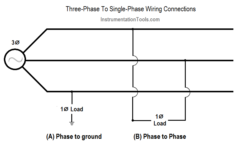
Figure 1 : Three-Phase To Single-Phase Connections

The first scheme (Figure 1A) provides for the connection of the load from a phase leg to any ground point and is referred to as a phase-to-ground scheme. The remaining scheme (Figure 1B) connects the single-phase load between any two legs of the three-phase source and is referred to as a phase-to-phase connection. The choice of schemes, phase-to phase or phase-to-ground, allows several voltage options depending on whether the source three-phase system is a delta or wye configuration.

The only approved method of wiring single-phase power is the scheme commonly referred to as the 3-wire, single-phase Edison system. The illustration in Figure 2 depicts the use of a center-tapped transformer, with the center tap grounded, providing half voltage (120 V) connections on either side or full voltage (240 V) across both sides.

3 Wire Edison Scheme

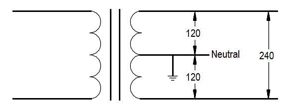
Figure 2 : 3-Wire Edison Scheme

The physical connections to the transformer secondary involve two insulated conductors and one bare conductor. If the conductor is a current-carrying leg or neutral leg, the conductor will be insulated. The remaining uninsulated conductor will serve as a safety ground and will be bonded to the ground point of the system. In all cases, 3 wires will be presented to the load terminals, and the safety ground will be bonded to each junction box, or device, in the distribution system.

In the case of half voltage (120 V) use, the intended path of the current is from the supply leg through the load and back to the source on the neutral leg. No current would be carried on the ground unless a fault occurred in the system, in which case the current would flow safely to ground.

In the full voltage system (240 V), the insulated conductors are connected across the full winding of the transformer, and the uninsulated conductor is again bonded to the grounded center tap. In a balanced system, all currents will flow on the insulated conductors, and the grounded neutral will carry no current, acting only in a ground capacity.

In the case of either an unbalanced load or a fault in the system, the bare conductor will carry current, but the potential will remain at zero volts because it is tied to the ground point. As in the case of the half voltage system, the uninsulated conductor will be bonded to each device in the system for safety.

Don't Miss Our Updates
Be the first to get exclusive content straight to your email.
We promise not to spam you. You can unsubscribe at any time.
Invalid email address
You've successfully subscribed !

Continue Reading

Batteries Theory
Electrical Diagrams and Schematics
Resistance in Parallel Circuits
Shunt-Wound Motor Operation
D’Arsonval Meter Movement
4-Wire, Three-Phase Wye Wiring System
Share This Article
Facebook Whatsapp Whatsapp LinkedIn Copy Link
Share
Leave a Comment

Leave a Reply Cancel reply

Your email address will not be published. Required fields are marked *

Stay Connected

128.3kFollowersLike
69.1kFollowersFollow
208kSubscribersSubscribe
38kFollowersFollow

Categories

Explore More

Power in Balanced 3 Phase Loads
AC Generation
Full-Wave Rectifier Circuit
Starting of DC Motors
Three Phase Systems
Ammeter
Impedance
AC Generator Voltage Regulators
Simplified Formulas for Parallel Circuit Resistance Calculations
Power Triangle

Keep Learning

Units of Electrical Measurement

Units of Electrical Measurement

Three Phase AC Generators

Three Phase AC Generators

Potential Difference Across a Conductor Causes a Current to Flow

Conductor, Insulator, Resistor and Current Flow

Carbon Atom

What is Electricity ?

How to Measure Specific Gravity of Battery

How to Measure Specific Gravity of Battery

Schematic Diagram

Schematic Diagram

AC Generator Operation

AC Generator Theory

Calculate Power in Parallel RCL Circuit

Calculate Power in Parallel RCL Circuit

Discover More

Pneumatic Load Cell Principle

Pneumatic Load Cell Principle

Irrigation based Projects

Irrigation based Projects for College Students

Interview Questions on Transformers

Interview Questions on Transformers

Essential Safety Tips for Glass Workers

Essential Safety Tips for Glass Workers

PLC Power Supply and Operating Voltages

PLC Power Supply and Operating Voltages

What is insulation

What is insulation? How to Choose the Insulation Material?

Electrical Switchgear & Protection Interview Questions

Electrical Switchgear & Protection Interview Questions

Playground Swing Logic Exercise Program in PLC

Playground Swing Logic Exercise Program in PLC

Follow US
All rights reserved. Reproduction in whole or in part without written permission is prohibited.
Welcome Back!

Sign in to your account

Username or Email Address
Password

Lost your password?