Inst ToolsInst ToolsInst Tools
  • Ask
  • Courses
  • Videos
  • Q & A
    • Interview
      • Instrumentation
      • Electronics
      • Electrical
      • Practical Questions
    • MCQ
      • Instrumentation MCQ
      • Electrical MCQ
      • Electronics MCQ
      • Control Systems MCQ
      • Analog Electronics MCQ
      • Digital Electronics MCQ
      • Power Electronics MCQ
      • Microprocessor MCQ
      • Multiple Choice Questions
  • EE
    • Electronics
      • Electronics Q & A
      • Electronic Basics
      • Electronic Devices & Circuits
      • Electronics Animation
      • Digital Electronics
    • Electrical
      • Electrical Basics
      • Electrical Q & A
      • Power Electronics
      • Electrical Machines
      • Electrical Animation
      • Power Systems
      • Switchgear & Protection
      • Transmission & Distribution
  • Measure
    • Control Valves
    • Calibration
    • Temperature
    • Pressure
    • Flow
    • Level
    • Analyzers
    • Switches
    • Vibration
    • Solenoid Valve
  • Control
    • PLC Tutorials
    • Control Systems
    • Safety Instrumented System (SIS)
    • Communication
    • Fire & Gas System
  • More
    • Design
    • Tools
    • Animation
    • Basics
    • Formulas
    • Standards
    • TextBooks
    • Common
    • Software
    • Excel Tools
    • Erection & Commissioning
    • Process Fundamentals
    • Videos
    • Books
Search
All rights reserved. Reproduction in whole or in part without written permission is prohibited.
Reading: Unbalanced 3 Phase Loads
Share
Notification Show More
Font ResizerAa
Inst ToolsInst Tools
Font ResizerAa
  • Courses
  • PLC Tutorials
  • Control Systems
Search
  • Ask
  • Courses
  • Videos
  • Q & A
    • Interview
    • MCQ
  • EE
    • Electronics
    • Electrical
  • Measure
    • Control Valves
    • Calibration
    • Temperature
    • Pressure
    • Flow
    • Level
    • Analyzers
    • Switches
    • Vibration
    • Solenoid Valve
  • Control
    • PLC Tutorials
    • Control Systems
    • Safety Instrumented System (SIS)
    • Communication
    • Fire & Gas System
  • More
    • Design
    • Tools
    • Animation
    • Basics
    • Formulas
    • Standards
    • TextBooks
    • Common
    • Software
    • Excel Tools
    • Erection & Commissioning
    • Process Fundamentals
    • Videos
    • Books
Follow US
All rights reserved. Reproduction in whole or in part without written permission is prohibited.
Inst Tools > Blog > Electrical Theory > Unbalanced 3 Phase Loads

Unbalanced 3 Phase Loads

Last updated: August 2, 2018 8:17 pm
Editorial Staff
Electrical Theory
No Comments
Share
2 Min Read
SHARE

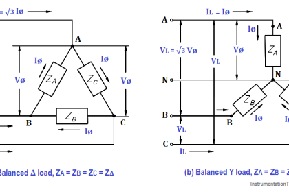
An important property of a three-phase balanced system is that the phasor sum of the three line or phase voltages is zero, and the phasor sum of the three line or phase currents is zero. When the three load impedances are not equal to one another, the phasor sums and the neutral current (In) are not zero, and the load is, therefore, unbalanced. The imbalance occurs when an open or short circuit appears at the load.

If a three-phase system has an unbalanced load and an unbalanced power source, the methods of fixing the system are complex. Therefore, we will only consider an unbalanced load with a balanced power source.

Example:

A 3φ balanced system, as shown in Figure 16a, contains a wye load. The line-to- line voltage is 240V, and the resistance is 40 Ω in each branch.

Unbalanced 3 Phase Loads

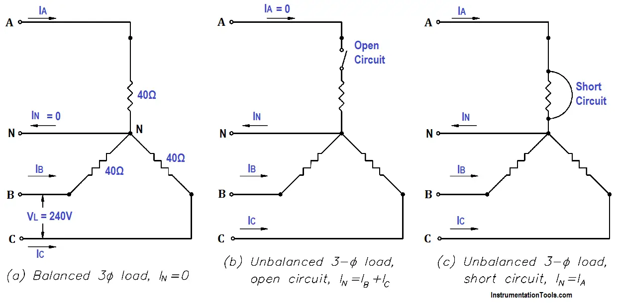
Figure 16 : 3φ Unbalanced Load

Find line current and neutral current for the following load conditions.

  1. balanced load
  2. open circuit phase A (Figure 16b)
  3. short circuit in phase A (Figure 16c)

Solution : balanced load
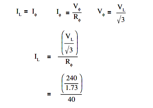
Unbalanced 3 Phase Loads Current Equation

IL = 138.7/40

IL = 3.5 amps

IN = 0

Solution : Answer for open circuit phase A

2. Current flow in lines B and C becomes the resultant of the loads in B and C connected in series.
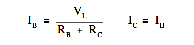
Unbalanced 3 Phase Loads Current Equation - 1

IB = 240/40+40

IB = 3 amps

so, IC = 3 amps

IN = IB + IC = 6 amps

3. Answer for short circuit in phase A
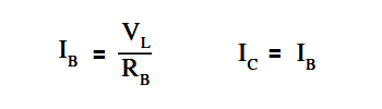
Unbalanced 3 Phase Loads Current Equation - 2

IB = 240/40

IB = 6 amps

so IC = 6 amps

The current in Phase A is equal to the neutral line current, IA = IN

Therefore, IN is the phasor sum of IB = IC

IN = √3 IB

IN = 1.73 x 6

IN = 10.4 amps

In a fault condition, the neutral connection in a wye-connected load will carry more current than the phase under a balanced load. Unbalanced three-phase circuits are indicated by abnormally high currents in one or more of the phases. This may cause damage to equipment if the imbalance is allowed to continue.

Don't Miss Our Updates
Be the first to get exclusive content straight to your email.
We promise not to spam you. You can unsubscribe at any time.
Invalid email address
You've successfully subscribed !
How to Measure Specific Gravity of Battery
Transformer Impedance Ratio
Calculate Power in Parallel RC Circuit
Electro-Dynamo Meter Movement
DC Motor Theory
Share This Article
Facebook Whatsapp Whatsapp LinkedIn Copy Link
Share
Leave a Comment

Leave a Reply Cancel reply

Your email address will not be published. Required fields are marked *

Stay Connected

128.3kFollowersLike
69.1kFollowersFollow
208kSubscribersSubscribe
38kFollowersFollow

Categories

Recent Comments

  • Kamli on Top Free PLC Software
  • Guifty Shimica on Top Non-PLC Certification Courses for Automation Professionals
  • Guifty Shimica on Top Non-PLC Certification Courses for Automation Professionals
  • MIHARITSOA Aina Sitraka on Top Non-PLC Certification Courses for Automation Professionals

Related Articles

Squirrel-Cage Induction Rotor

Induction Motor

Series-Wound DC Generator Principle

Series-Wound DC Generators

Three Phase AC Generators

Three Phase AC Generators

current division Formula for Resistor Circuit

Current Division

Transformer Coil Polarity

Transformer Coil Polarity

Carbon Atom

What is Electricity ?

Series Parallel Circuit Analysis

Series – Parallel Circuit Analysis

AC to DC Conversion with a Commutator

DC Machines Terminology

More Articles

instrumentation engineering standards

ISA codes for Process Instrumentation

Reasons to Calibrate Flowmeters

Reasons to Calibrate Different Types of Flow Meters

Stability in Frequency Domain

Tuning of PID Controllers

main controller fails

How does a Redundant Controller comes in line when the Main Controller fails?

Nonlinear Control Systems

Construction of Phase -Trajectories

Displacer Level Sensor

What is Displacer Level Sensor ?

Why Grounding

Generating Station Grounding Principles

Float & Dial Level Gauge Principle

Float & Dial Level Gauge Principle

Follow US
All rights reserved. Reproduction in whole or in part without written permission is prohibited.
Welcome Back!

Sign in to your account

Username or Email Address
Password

Lost your password?