Inst ToolsInst ToolsInst Tools
  • Courses
  • Automation
    • PLC
    • Control System
    • Safety System
    • Communication
    • Fire & Gas System
  • Instrumentation
    • Design
    • Pressure
    • Temperature
    • Flow
    • Level
    • Vibration
    • Analyzer
    • Control Valve
    • Switch
    • Calibration
    • Erection & Commissioning
  • Interview
    • Instrumentation
    • Electrical
    • Electronics
    • Practical
  • Q&A
    • Instrumentation
    • Control System
    • Electrical
    • Electronics
    • Analog Electronics
    • Digital Electronics
    • Power Electronics
    • Microprocessor
  • Request
Search
  • Books
  • Software
  • Projects
  • Process
  • Tools
  • Basics
  • Formula
  • Power Plant
  • Root Cause Analysis
  • Electrical Basics
  • Animation
  • Standards
  • 4-20 mA Course
  • Siemens PLC Course
Reading: Generator Action in a Motor
Share
Font ResizerAa
Inst ToolsInst Tools
Font ResizerAa
  • Courses
  • Design
  • PLC
  • Interview
  • Control System
Search
  • Courses
  • Automation
    • PLC
    • Control System
    • Safety System
    • Communication
    • Fire & Gas System
  • Instrumentation
    • Design
    • Pressure
    • Temperature
    • Flow
    • Level
    • Vibration
    • Analyzer
    • Control Valve
    • Switch
    • Calibration
    • Erection & Commissioning
  • Interview
    • Instrumentation
    • Electrical
    • Electronics
    • Practical
  • Q&A
    • Instrumentation
    • Control System
    • Electrical
    • Electronics
    • Analog Electronics
    • Digital Electronics
    • Power Electronics
    • Microprocessor
  • Request
Follow US
All rights reserved. Reproduction in whole or in part without written permission is prohibited.
Inst Tools > Blog > Electrical Theory > Generator Action in a Motor

Generator Action in a Motor

Last updated: July 29, 2018 11:14 am
Editorial Staff
Electrical Theory
No Comments
Share
2 Min Read
SHARE

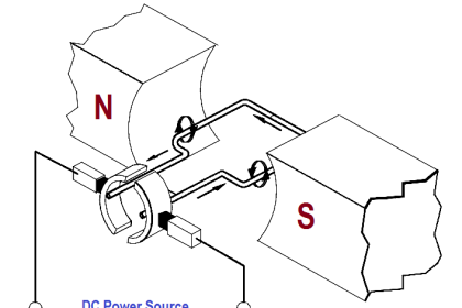
A generator action is developed in every motor. When a conductor cuts lines of force, an EMF is induced in that conductor.

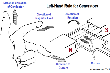
Current to start the armature turning will flow in the direction determined by the applied DC power source. After rotation starts, the conductor cuts lines of force. By applying the left-hand rule for generators, the EMF that is induced in the armature will produce a current in the opposite direction. The induced EMF, as a result of motor operation, is called counter-electromotive force, or CEMF, as illustrated in Figure 6.

Generator Action in a Motor

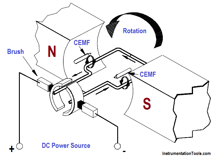
Since the CEMF is generated by the action of the armature cutting lines of force, the value of CEMF will depend on field strength and armature speed, as shown in Equation.

ECEMF = K Φ N

where

ECEMF = counter EMF
K = constant
Φ = field flux strength
N = speed of the armature

The CEMF opposes the applied voltage and functions to lower armature current. The effective voltage acting in the armature of a motor is the applied voltage, minus the counter EMF. Armature current can be found by using Ohm’s law, as shown in below Equation.
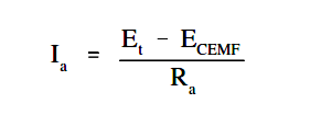
Generator Action in a Motor Formula

where
Ia = armature current
ECEMF == terminal voltage
Et= counter EMF
Ra= armature resistance

Don't Miss Our Updates
Be the first to get exclusive content straight to your email.
We promise not to spam you. You can unsubscribe at any time.
Invalid email address
You've successfully subscribed !

Continue Reading

Low Voltage Protection (LVP) and Low Voltage Release (LVR)
Impedance
AC Generation
Ammeter
4-Wire, Three-Phase Delta Wiring System
Full-Wave Rectifier Circuit
Share This Article
Facebook Whatsapp Whatsapp LinkedIn Copy Link
Share
Leave a Comment

Leave a Reply Cancel reply

Your email address will not be published. Required fields are marked *

Stay Connected

128.3kFollowersLike
69.1kFollowersFollow
210kSubscribersSubscribe
38kFollowersFollow

Categories

Explore More

Types of AC Generators
Y and Delta Resistor Network Calculations
Three Phase Systems
Simplified Formulas for Parallel Circuit Resistance Calculations
Calculate Power in Series RCL Circuit
4-Wire, Three-Phase Wye Wiring System
Three Phase Transformer Connections
Unbalanced 3 Phase Loads

Keep Learning

3 Phase Balanced Loads

Power in Balanced 3 Phase Loads

Using Kirchhoff’s Voltage Law to find Current with Multiple Battery Sources

Kirchhoff’s Laws

Marking Polarity

DC Circuit Analysis Loop Equations

Types of Batteries

Types of Batteries

Shunt-Wound DC Generator Principle

Shunt-Wound DC Generators

Electric Open Circuit

Series Open Circuit Faults

Total Resistance in a Parallel Circuit

Resistance in Parallel Circuits

Series Circuit

Series Circuit

Learn More

difference between invasive and non-invasive and intrusive and non-intrusive

Difference between Invasive, Non-invasive, Intrusive & Non-intrusive

How to Use Loop Calibrator

Troubleshooting with Loop Calibrator

Power Electronics Objective Questions

Thyristor Chopper Circuit Quiz

Power Supply Unit with Diode Protection

Why we use Diode Protection Modules ?

Analyzers Questions and Answers

H2S Analyzers Questions & Answers

Difference of Energy Gap

Difference between Intrinsic and Extrinsic Semiconductors

Process Air Compressor Overhauls Eliminated

Process Air Compressor too Frequent & too Lengthy Overhauls Eliminated

Testing and Validation in PLC Development

Testing and Validation in PLC Development

Menu

  • About
  • Privacy Policy
  • Copyright

Quick Links

  • Learn PLC
  • Helping Hand
  • Part Time Job

YouTube Subscribe

Follow US
All rights reserved. Reproduction in whole or in part without written permission is prohibited.
Welcome Back!

Sign in to your account

Username or Email Address
Password

Lost your password?