Inst ToolsInst ToolsInst Tools
  • Courses
  • Automation
    • PLC
    • Control System
    • Safety System
    • Communication
    • Fire & Gas System
  • Instrumentation
    • Design
    • Pressure
    • Temperature
    • Flow
    • Level
    • Vibration
    • Analyzer
    • Control Valve
    • Switch
    • Calibration
    • Erection & Commissioning
  • Interview
    • Instrumentation
    • Electrical
    • Electronics
    • Practical
  • Q&A
    • Instrumentation
    • Control System
    • Electrical
    • Electronics
    • Analog Electronics
    • Digital Electronics
    • Power Electronics
    • Microprocessor
  • Request
Search
  • Books
  • Software
  • Projects
  • Process
  • Tools
  • Basics
  • Formula
  • Power Plant
  • Root Cause Analysis
  • Electrical Basics
  • Animation
  • Standards
  • 4-20 mA Course
  • Siemens PLC Course
Reading: Calculate the Thermocouple Output millivolts
Share
Font ResizerAa
Inst ToolsInst Tools
Font ResizerAa
  • Courses
  • Design
  • PLC
  • Interview
  • Control System
Search
  • Courses
  • Automation
    • PLC
    • Control System
    • Safety System
    • Communication
    • Fire & Gas System
  • Instrumentation
    • Design
    • Pressure
    • Temperature
    • Flow
    • Level
    • Vibration
    • Analyzer
    • Control Valve
    • Switch
    • Calibration
    • Erection & Commissioning
  • Interview
    • Instrumentation
    • Electrical
    • Electronics
    • Practical
  • Q&A
    • Instrumentation
    • Control System
    • Electrical
    • Electronics
    • Analog Electronics
    • Digital Electronics
    • Power Electronics
    • Microprocessor
  • Request
Follow US
All rights reserved. Reproduction in whole or in part without written permission is prohibited.
Inst Tools > Blog > Practical Questions > Calculate the Thermocouple Output millivolts

Calculate the Thermocouple Output millivolts

Last updated: September 20, 2018 11:15 am
Editorial Staff
Practical Questions
No Comments
Share
1 Min Read
SHARE

Suppose someone builds a dual-junction thermocouple circuit using type T thermocouple wire (copper and constantan metals), then measures voltage between the two junctions with a voltmeter:

Calculate the Thermocouple Output millivolts

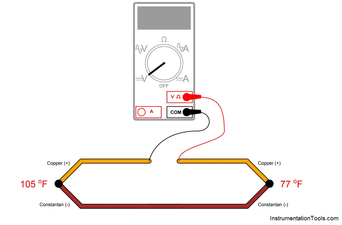
Calculate the voltage read by the voltmeter, using a type T thermocouple table to find millivolt potentials for each of the junctions.

Answer :

The voltmeter should read -0.643 millivolts, because the 105 oF junction has a potential of 1.635 millivolts, the 77 oF junction has a potential of 0.992 millivolts, and the two junctions’ voltages are opposing one another in polarity with the positive terminal of the voltmeter connected to the negative-most copper wire.

Don't Miss Our Updates
Be the first to get exclusive content straight to your email.
We promise not to spam you. You can unsubscribe at any time.
Invalid email address
You've successfully subscribed !

Continue Reading

PLC Switch Actuation Status
Programmable Logic Controller (PLC) Questions and Answers – 8
Something is Wrong with Strain Gauge Bridge Circuit
Flow Transmitter Readings mismatch with DCS
Identify all Spool Valve Positions
A Series of False Pressure Alarms
Share This Article
Facebook Whatsapp Whatsapp LinkedIn Copy Link
Share
Leave a Comment

Leave a Reply Cancel reply

Your email address will not be published. Required fields are marked *

Stay Connected

128.3kFollowersLike
69.1kFollowersFollow
210kSubscribersSubscribe
38kFollowersFollow

Categories

Explore More

Pressure Transmitter Re-Range Questions
Pressure Switch Questions
pH Transmitter Problem
Identify High Flow Alarm and Low Flow Alarm?
Questions on Resistive Tape Level Sensor
Programmable Logic Controller (PLC) Questions and Answers – 11
Determine the Temperature of 3 Wire RTD
Air Pressure Inside the Tank

Keep Learning

hydrostatic interface measurement calculation

Hydrostatic Pressure Measurement Questions

Liquid Level Measurement using Pressure Transmitter

Liquid Level Measurement using Pressure Transmitter Questions

Dry Leg

Calculate 0%, 50%, and 100% Calibration Points for ΔP transmitter

PLC program to control pump

Troubleshooting PLC Permissive Inputs

Galileo thermometer Principle

Galileo Thermometer

Calculate Total Hydrostatic Pressure at Bottom of Vessel

Calculate Total Hydrostatic Pressure at Bottom of Vessel

Loop Diagram

PT Loop Diagram Faults

Calibration setup for a low-range electronic pressure transmitter

Instrument Lab Exercise – Ranging and Manometer Usage

Learn More

Instrument System Architecture and Process Control Design

System Architecture and Process Control Systems Philosophy

Rewire Tool

What is Rewire Tool in Simatic Manager?

SIS Bypass and Impairment - Safety Instrumented System

SIS Bypass and Impairment – Safety Instrumented System

What Every Instrument Engineer Should Know

Common Mistakes in Instrumentation

Power Electronics Objective Questions

Choppers Objective Questions

Basics of Loop Checks

Basics of Loop Checks

PLC Program for Traffic Light Sequence using Functional Blocks

PLC Program for Traffic Light Sequence using Functional Blocks

rangeability-of-flow-meter-vs-percentage-of-maximum-flow

Flow Transmitter Rangeability

Menu

  • About
  • Privacy Policy
  • Copyright

Quick Links

  • Learn PLC
  • Helping Hand
  • Part Time Job

YouTube Subscribe

Follow US
All rights reserved. Reproduction in whole or in part without written permission is prohibited.
Welcome Back!

Sign in to your account

Username or Email Address
Password

Lost your password?