Inst ToolsInst ToolsInst Tools
  • Ask
  • Courses
  • Videos
  • Q & A
    • Interview
      • Instrumentation
      • Electronics
      • Electrical
      • Practical Questions
    • MCQ
      • Instrumentation MCQ
      • Electrical MCQ
      • Electronics MCQ
      • Control Systems MCQ
      • Analog Electronics MCQ
      • Digital Electronics MCQ
      • Power Electronics MCQ
      • Microprocessor MCQ
      • Multiple Choice Questions
  • EE
    • Electronics
      • Electronics Q & A
      • Electronic Basics
      • Electronic Devices & Circuits
      • Electronics Animation
      • Digital Electronics
    • Electrical
      • Electrical Basics
      • Electrical Q & A
      • Power Electronics
      • Electrical Machines
      • Electrical Animation
      • Power Systems
      • Switchgear & Protection
      • Transmission & Distribution
  • Measure
    • Control Valves
    • Calibration
    • Temperature
    • Pressure
    • Flow
    • Level
    • Analyzers
    • Switches
    • Vibration
    • Solenoid Valve
  • Control
    • PLC Tutorials
    • Control Systems
    • Safety Instrumented System (SIS)
    • Communication
    • Fire & Gas System
  • More
    • Design
    • Tools
    • Animation
    • Basics
    • Formulas
    • Standards
    • TextBooks
    • Common
    • Software
    • Excel Tools
    • Erection & Commissioning
    • Process Fundamentals
    • Videos
    • Books
Search
All rights reserved. Reproduction in whole or in part without written permission is prohibited.
Reading: PMMC Temperature Compensation
Share
Notification Show More
Font ResizerAa
Inst ToolsInst Tools
Font ResizerAa
  • Courses
  • PLC Tutorials
  • Control Systems
Search
  • Ask
  • Courses
  • Videos
  • Q & A
    • Interview
    • MCQ
  • EE
    • Electronics
    • Electrical
  • Measure
    • Control Valves
    • Calibration
    • Temperature
    • Pressure
    • Flow
    • Level
    • Analyzers
    • Switches
    • Vibration
    • Solenoid Valve
  • Control
    • PLC Tutorials
    • Control Systems
    • Safety Instrumented System (SIS)
    • Communication
    • Fire & Gas System
  • More
    • Design
    • Tools
    • Animation
    • Basics
    • Formulas
    • Standards
    • TextBooks
    • Common
    • Software
    • Excel Tools
    • Erection & Commissioning
    • Process Fundamentals
    • Videos
    • Books
Follow US
All rights reserved. Reproduction in whole or in part without written permission is prohibited.
Inst Tools > Blog > Electronic Devices & Circuits > PMMC Temperature Compensation

PMMC Temperature Compensation

Last updated: April 1, 2018 9:31 am
Editorial Staff
Electronic Devices & Circuits
No Comments
Share
3 Min Read
SHARE

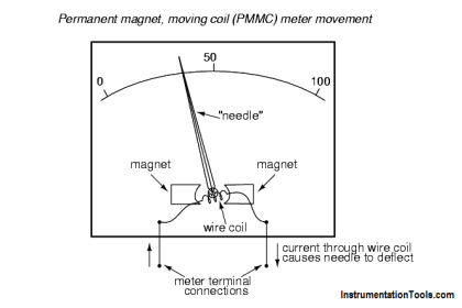
The basic pmmc instrument is sensitive to the temperature. The magnetic field strength and spring tension decrease with increase in temperature. The coil resistance increases with increase in the temperature. Thus pointer reads low for a given current. The meter tends to read low by approximately 0.2% per Celsius rise in the temperature. Hence the temperature compensation is provided by appropriate use of series and shunt resistance of copper and manganin.

Contents
Temperature compensationErrors in PMMC Instrument

Temperature compensation

The simple temperature compensation circuit for PMMC uses a resistance in series with a movable coil, as shown in the figure. The resistor is called swamping resistor. It is made up of manganin having practically zero temperature coefficients, combined with copper in the ratio of 20/1 or 30/1.

temperature compensation circuit for PMMC

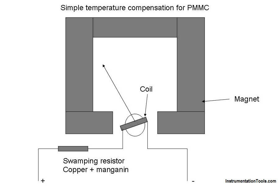
The resultant resistance of the coil and the swamping resistor increases slightly as temperature increases, just enough to compensate the change in springs and magnet due to temperature. Thus the effect of temperature is compensated.

More complicated but complete cancellation of temperature effects can be obtained by using the swamping resistors in series and parallel combination as shown in figure.

Errors in PMMC Instrument
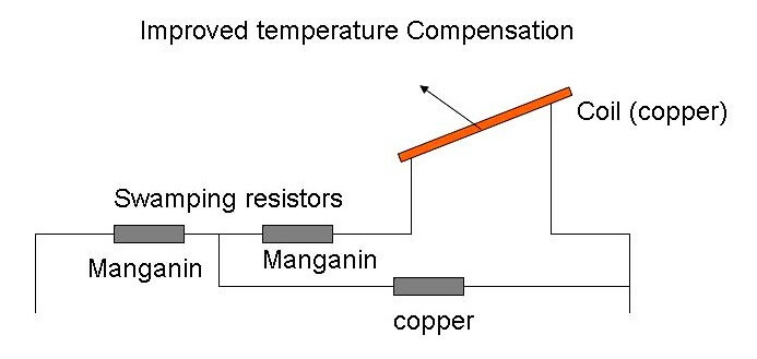
In this circuit, by correct proportioning of copper and manganin parts, complete cancellation of the temperature effects can be achieved.

Errors in PMMC Instrument

The basic sources of error in PMMC instruments are friction, temperature and aging of various parts. To reduce the frictional errors ratio of torque to weight is made very high.

The most serious errors are produced by the heat generated or by changes in the temperature. This changes the resistance of the working coil, causing large errors. In case of voltmeters, a large series resistance of very low temperature coefficient is used. This reduces the temperature errors.

The aging of permanent magnet and control springs also cause errors. Opposite errors in PMMC is caused by weakening of magnet and spring cause. The weakening of magnet causes less deflection while weakening of control springs cause large deflection, for a particular value of current. The proper use of material and pre-ageing during manufacturing can reduce the errors due to weakening of control springs.

Don't Miss Our Updates
Be the first to get exclusive content straight to your email.
We promise not to spam you. You can unsubscribe at any time.
Invalid email address
You've successfully subscribed !
VI Characteristic of a Diode
Transistor Cut off, Saturation & Active Regions
Transistor Base Bias
N Type and P Type Semiconductors
Phototransistor Working Principle
Share This Article
Facebook Whatsapp Whatsapp LinkedIn Copy Link
Share
Leave a Comment

Leave a Reply Cancel reply

Your email address will not be published. Required fields are marked *

Stay Connected

128.3kFollowersLike
69.1kFollowersFollow
208kSubscribersSubscribe
38kFollowersFollow

Categories

Recent Comments

  • Kamli on Top Free PLC Software
  • Guifty Shimica on Top Non-PLC Certification Courses for Automation Professionals
  • Guifty Shimica on Top Non-PLC Certification Courses for Automation Professionals
  • MIHARITSOA Aina Sitraka on Top Non-PLC Certification Courses for Automation Professionals

Related Articles

Comparison of MOSFET and BJT

Comparison of MOSFET and BJT

diode-limiter-principle

Diode Limiters/Clippers Operation

Transistor Load Line Analysis

Transistor Load Line Analysis

Independent-Voltage-Source-circuit-ideal-battery

Circuit Elements and Types of Circuits

principle of time base generator

Time Base Generator

Applications of Photo diodes

Applications of Photo diodes

half-wave-rectifier-working-animation

Half Wave Rectifier Principle

Derivation-of-Ohms-Law

Basics of Ohm’s Law

More Articles

Modbus Network Motor Control

Motor Control using Modbus Communication and Hardwired Signals

Steam Turbine Driven Centrifugal Compressors Leak due to Broken Instrument

Steam Turbine Driven Centrifugal Compressors Leak due to Broken Instrument

Three phase inverter Animation

Three Phase Inverter Animation

Zener Barrier Protection

Zener Diode Barrier Principle

Namur Digital Input Card

What is Namur Digital Input Card?

Orifice Plate

Orifice Plate Questions and Answers

The Control Valve Stroke Test Procedure

Control Valve Stroke Test Procedure

Electrical Machines Questions and Answers

Autotransformers

Follow US
All rights reserved. Reproduction in whole or in part without written permission is prohibited.
Welcome Back!

Sign in to your account

Username or Email Address
Password

Lost your password?