Inst ToolsInst ToolsInst Tools
  • Ask
  • Courses
  • Videos
  • Q & A
    • Interview
      • Instrumentation
      • Electronics
      • Electrical
      • Practical Questions
    • MCQ
      • Instrumentation MCQ
      • Electrical MCQ
      • Electronics MCQ
      • Control Systems MCQ
      • Analog Electronics MCQ
      • Digital Electronics MCQ
      • Power Electronics MCQ
      • Microprocessor MCQ
      • Multiple Choice Questions
  • EE
    • Electronics
      • Electronics Q & A
      • Electronic Basics
      • Electronic Devices & Circuits
      • Electronics Animation
      • Digital Electronics
    • Electrical
      • Electrical Basics
      • Electrical Q & A
      • Power Electronics
      • Electrical Machines
      • Electrical Animation
      • Power Systems
      • Switchgear & Protection
      • Transmission & Distribution
  • Measure
    • Control Valves
    • Calibration
    • Temperature
    • Pressure
    • Flow
    • Level
    • Analyzers
    • Switches
    • Vibration
    • Solenoid Valve
  • Control
    • PLC Tutorials
    • Control Systems
    • Safety Instrumented System (SIS)
    • Communication
    • Fire & Gas System
  • More
    • Design
    • Tools
    • Animation
    • Basics
    • Formulas
    • Standards
    • TextBooks
    • Common
    • Software
    • Excel Tools
    • Erection & Commissioning
    • Process Fundamentals
    • Videos
    • Books
Search
All rights reserved. Reproduction in whole or in part without written permission is prohibited.
Reading: Foundation Fieldbus Segment Design
Share
Notification Show More
Font ResizerAa
Inst ToolsInst Tools
Font ResizerAa
  • Courses
  • PLC Tutorials
  • Control Systems
Search
  • Ask
  • Courses
  • Videos
  • Q & A
    • Interview
    • MCQ
  • EE
    • Electronics
    • Electrical
  • Measure
    • Control Valves
    • Calibration
    • Temperature
    • Pressure
    • Flow
    • Level
    • Analyzers
    • Switches
    • Vibration
    • Solenoid Valve
  • Control
    • PLC Tutorials
    • Control Systems
    • Safety Instrumented System (SIS)
    • Communication
    • Fire & Gas System
  • More
    • Design
    • Tools
    • Animation
    • Basics
    • Formulas
    • Standards
    • TextBooks
    • Common
    • Software
    • Excel Tools
    • Erection & Commissioning
    • Process Fundamentals
    • Videos
    • Books
Follow US
All rights reserved. Reproduction in whole or in part without written permission is prohibited.
Inst Tools > Blog > Communication > Foundation Fieldbus Segment Design

Foundation Fieldbus Segment Design

Last updated: January 3, 2019 7:07 am
Editorial Staff
Communication
1 Comment
Share
2 Min Read
SHARE

In addition to maximum (total) cable length and repeater count, a host of other details (Note 1) conspire to limit how any particular H1 segment is wired. To help engineers and technicians alike deal with these details, manufacturers often provide free segment design tool software to pre-validate a segment design on computer before purchasing components and installing them in the field.

Note 1 : Total device current draw, spur length versus number, intrinsic safety voltage and current limitations, etc.

A screenshot taken from Emerson’s offering shows what a typical FF segment layout might look like:

Fieldbus Segment Design

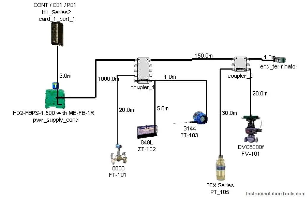
A very nice feature of these segment design packages is their built-in database of FF components. Every time you “pick” a particular component to place in your simulated segment, the program references data for that device’s current draw and other electrical parameters relevant to the performance of the segment. Of course, each manufacturer will tend to feature their own devices more prominently, and so these software tools sometimes feel like a promotional advertisement. Despite the commercial aspect of their design, however, they are extremely useful in the planning stages of a FF network, and should be used whenever possible.

Another reason to use segment design tool software is to document the wiring of each FF segment. One of the casualties of the new Fieldbus paradigm is the traditional loop diagram (or “loop sheet”), the purpose of which is to document the signal wiring dedicated for each measurement and control loop. In FOUNDATION Fieldbus, the control “loop” is virtual rather than physical, being comprised of digital data sent between field instruments, the path of which being defined by the instruments’ programming. The only physical wiring entity to document in a FF system is the segment, and each segment most likely hosts more than one measurement and/or control loop. Unless and until a standardized documentation format is invented for Fieldbus network segments, the graphic image provided by segment design tool software is as good as anything.

Don't Miss Our Updates
Be the first to get exclusive content straight to your email.
We promise not to spam you. You can unsubscribe at any time.
Invalid email address
You've successfully subscribed !
Fieldbus Transmitters Calibration and Ranging
Difference Between RS232 and RS485
Difference Between Modbus TCP IP and Profinet
Fieldbus Analog Input Function Block
Fiber Optic Cable Connectors, Routing, and Safety
Share This Article
Facebook Whatsapp Whatsapp LinkedIn Copy Link
Share
1 Comment
  • Chirag Jadav says:
    March 27, 2018 at 2:54 am

    In foundation fieldbus Design sagment which communication used from filed instruments to local module and local module(coupler) to main module?

    Reply

Leave a Reply Cancel reply

Your email address will not be published. Required fields are marked *

Stay Connected

128.3kFollowersLike
69.1kFollowersFollow
208kSubscribersSubscribe
38kFollowersFollow

Categories

Recent Comments

  • Kamli on Top Free PLC Software
  • Guifty Shimica on Top Non-PLC Certification Courses for Automation Professionals
  • Guifty Shimica on Top Non-PLC Certification Courses for Automation Professionals
  • MIHARITSOA Aina Sitraka on Top Non-PLC Certification Courses for Automation Professionals

Related Articles

WirelessHART mesh network

WirelessHART

Profibus network

How Profibus Communication Works

Important Networking Interview Questions

Important Networking Interview Questions

HART Layers vs OSI Layers

HART Communication Tutorial Part 3

Foundation Fieldbus Signal Conversion Formula

Foundation Fieldbus Signal Conversion Formula

Auto-negotiation in Network

What is Auto-negotiation in Network?

overview-of-communication-protocols

Industrial Automation Communication Protocols

RAID stands for Redundant Array of Independent Disks

What is Raid Parity? – Types, Advantages, Disadvantages

More Articles

Pressure Measurement using Manometer

Pressure Measurement using Manometer

What is Eddy Current and Eddy Current Loss

What is Eddy Current and Eddy Current Loss?

Calculate Resistance from Temperature for RTD

RTD Calculator : Calculate Resistance from Temperature

Difference Between Predictive Maintenance and Preventive Maintenance

Difference Between Predictive Maintenance and Preventive Maintenance

Top 80+ Valve Questions and Answers

Top 80+ Valve Questions and Answers

High-Speed Inputs in PLC

What are High-Speed Inputs in PLC?

Electrical Circuit Breaker Quiz

100 Electrical Circuit Breaker Quiz

Synchronous Motor Working Principle

Follow US
All rights reserved. Reproduction in whole or in part without written permission is prohibited.
Welcome Back!

Sign in to your account

Username or Email Address
Password

Lost your password?