Inst ToolsInst ToolsInst Tools
  • Courses
  • Automation
    • PLC
    • Control System
    • Safety System
    • Communication
    • Fire & Gas System
  • Instrumentation
    • Design
    • Pressure
    • Temperature
    • Flow
    • Level
    • Vibration
    • Analyzer
    • Control Valve
    • Switch
    • Calibration
    • Erection & Commissioning
  • Interview
    • Instrumentation
    • Electrical
    • Electronics
    • Practical
  • Q&A
    • Instrumentation
    • Control System
    • Electrical
    • Electronics
    • Analog Electronics
    • Digital Electronics
    • Power Electronics
    • Microprocessor
  • Request
Search
  • Books
  • Software
  • Projects
  • Process
  • Tools
  • Basics
  • Formula
  • Power Plant
  • Root Cause Analysis
  • Electrical Basics
  • Animation
  • Standards
  • 4-20 mA Course
  • Siemens PLC Course
Reading: Displacer Level Switch Working Principle
Share
Font ResizerAa
Inst ToolsInst Tools
Font ResizerAa
  • Courses
  • Design
  • PLC
  • Interview
  • Control System
Search
  • Courses
  • Automation
    • PLC
    • Control System
    • Safety System
    • Communication
    • Fire & Gas System
  • Instrumentation
    • Design
    • Pressure
    • Temperature
    • Flow
    • Level
    • Vibration
    • Analyzer
    • Control Valve
    • Switch
    • Calibration
    • Erection & Commissioning
  • Interview
    • Instrumentation
    • Electrical
    • Electronics
    • Practical
  • Q&A
    • Instrumentation
    • Control System
    • Electrical
    • Electronics
    • Analog Electronics
    • Digital Electronics
    • Power Electronics
    • Microprocessor
  • Request
Follow US
All rights reserved. Reproduction in whole or in part without written permission is prohibited.
Inst Tools > Blog > How It Works > Displacer Level Switch Working Principle

Displacer Level Switch Working Principle

Last updated: December 17, 2017 12:36 pm
Editorial Staff
How It Works Switches
1 Comment
Share
3 Min Read
SHARE

Displacer controls offer alternative features to the float-operated control. The sensor is a weight (displacer), heavier than the liquid, that is suspended by a spring. When liquid contacts the displacer, a buoyancy force is produced, which causes the effective weight of the displacer to change. This causes the spring to retract slightly to a new equilibrium position. When the spring retracts, the attraction sleeve also moves upward into the field of the external magnet, thus overcoming the force of the bias spring and actuating the switching element.

Displacer Operated Level Switch Working Principle

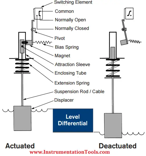
This principle provides for narrow or wide switching differential, and allows switching point alteration by moving the displacer(s) up or down the suspension cables.

Displacers may be arranged in combinations of narrow and wide differential to operate up to three switching stages. Displacer controls operate under higher pressure conditions than float-operated switches.

Applications: For wide switching differentials & higher pressure ratings. Used where traditional float operated units cannot work.

Floats v/s Displacers

Following are the major points of distinction between floats and displacers:

  • “Float Switches are available with a glandless design and are capable of fail safe operation in extreme process conditions, unlike displacers, which if the torque tube fails can provide a leak path.”
  • A float generally rides above the surface of liquid whereas a displacer remains either partly or totally immersed in process liquid.
  • Displacer switches are considered to be additionally stable and dependable as compared to standard float level switches in case of turbulent, surging, frothy and foamy services. However in case of refineries, the use of displacers is decreasing owing to their high installation cost and inaccurate performance due to process density changes. In these applications, float level switches have been found to be reliable and useful.
  • Settings of displacers can be changed very easily since they can be shifted at any place along the length of the suspension cable. Moreover, these level devices have the provision of interchangeability between tanks. This is due to the fact that the differences in process density can be endured by varying the tension of the spring attached to the displacers.
  • Testing the appropriate working of a displacer switch is much easier than a customary float level switch since the former requires just lifting of a suspension whereas the latter necessitates filling of liquid in the tank upto the actuation mark.

Also Read: Float Operated Level Switch Working Principle

Don't Miss Our Updates
Be the first to get exclusive content straight to your email.
We promise not to spam you. You can unsubscribe at any time.
Invalid email address
You've successfully subscribed !

Continue Reading

Magnetic Level Indicators Working Animation
Vortex Flow meter Animation
Oval Gear Meter – Principle, Advantages, Limitations, Applications
Define Normal Status for each of the Process Switch
Cable Float Level Switch Working Principle
Basics of Limit switches
Share This Article
Facebook Whatsapp Whatsapp LinkedIn Copy Link
Share
1 Comment
  • Aslam says:
    December 14, 2016 at 3:40 pm

    What is a basic difference of pressure and flow

    Reply

Leave a Reply Cancel reply

Your email address will not be published. Required fields are marked *

Stay Connected

128.3kFollowersLike
69.1kFollowersFollow
210kSubscribersSubscribe
38kFollowersFollow

Categories

Explore More

Switch Types and Common Terminology
Temperature Switch Working Principle
Coriolis Mass Flow Meter Working Principle
Paddle Switch Working Principle
PLC Example with Switches
Types of Limit Switches – Principle, Advantages, Disadvantages
Pull Up and Pull Down Switch Circuits
RF Level Switches Working Principle

Keep Learning

Belt Sway Switch Principle

Belt Sway Switch Working Principle

Electromagnetic Flow Meters Working Principle

Switch High level alarm occurs

Basics of Switches & its applications

Flow Switch Working

Flow Switch : What is it? – Applications

Control Valve Working Animation

Control Valve Working Animation

Switch NO or NC Contact

Normally-open and Normally-closed Switch Contacts

radar-level-sensor-

Non-Contacting Radar Level Transmitter Working Principle

Optical Level Switch Principle

Optical Level Switch Working Principle

Learn More

RF-Capacitance Level Switch Principle

RF Capacitance Level Switch Working Principle

Ethernet Questions and Answers

Ethernet Communication Interview Questions & Answers

Basics of Cable Shields

Basics of Cable Shields

Sample Raw DataSheet for Pressure Calibration

Sample Raw DataSheet for Pressure Calibration

Basics of Thyristor

Basics of Thyristor

HMI configuration for Delta VFD

Modbus Communication between Delta PLC with VFD

Gas Detectors Location Installation

Gas Detectors Installation Techniques

Temperature Controller Problem

Temperature Controller Problem

Menu

  • About
  • Privacy Policy
  • Copyright

Quick Links

  • Learn PLC
  • Helping Hand
  • Part Time Job

YouTube Subscribe

Follow US
All rights reserved. Reproduction in whole or in part without written permission is prohibited.
Welcome Back!

Sign in to your account

Username or Email Address
Password

Lost your password?